TD 92022EN
3 July 2013 / Ver. G
Installation Guide
H/U952T Terminal Transmitter
10
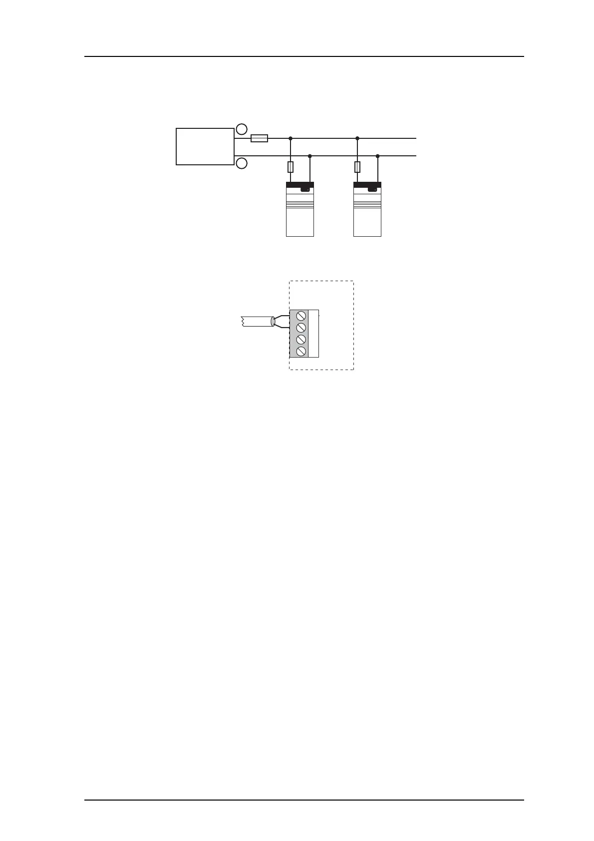
3.6 Connection of Supply Voltage
• Connect supply voltage to connector J102 screw 1 and 2. See the System Installation
document, chapter Power Supply.
J102
3 +12V
4 GND
1 +12V
2 GND
Supply voltage-in
H/U952T
• An external fuse must be placed between supply voltage connector and power supply.
The recommended fuse is 3.15A, use a quic
k acting, fast or very fast. It is recommended
to use an output power of 5W or less. Elevated power levels can lead to various
problems, as well as blow the fuse.
NOTE: If a HF transmitter with an in
door
antenna (for example, Sat-1) is connected to a
switched-mode power supply (for example, type 3020) using a coax cable of the
minimum specified length of 2.71m, random fluctuations in the electrical signal may
be sufficient to disturb the power supply and cause intermittent restarts of the
transmitter. The problem usually occurs when the installation is housed in a small
room. To reduce the risk of such disturbances, the use of a ferrite core between the
power supply and transmitter is recommended.
3.7 Addressing the Terminal Transmitter
Select the address by setting the address selector switch SW100. See the System
Installation document, chapter Addressing.
The address for H/U952T must not be 00, nor the same as any other Ascom Paging unit
D-bus address. In case the system includes speech, the Terminal Transmitte
r must be in the
address range for speech transmitters (hex address 80-FF).