Ascon Tecnologic - K31D - OPERATING INSTRUCTIONS - PAG. 10
5.11 Alarms Output Functions (AL1, AL2, AL3)
For the alarms operation settings, the operation of which is relat-
ed to the Process Value (AL1, AL2, AL3) it is first of all manda-
tory to determine to which output the alarm must be addressed.
To obtain this, it is necessary to set, in the parameters group
]out, the parameters related to the output that is to be used
by each alarm (O1F, O2F, O3F, O4F):
ALno If the alarm output must be ON when the alarm is ac-
tive, while it is OFF when the alarm is not active;
ALnc If the alarm output must be ON when the alarm is not
active, while it is OFF when the alarm is active (the
LED on the display shows the alarm status);
ALni Same operation as ALnc, but with a reversed LED
indication (LED ON = Alarm OFF).
Note: All the examples that follow are referred to alarm AL1.
Obviously the functions of the other alarms are similar
(change 1 with 2 or 3).
Access at the group ]Al1 and program oAL1, to indicate
which output the alarm signal must to be sent.
The AL1 alarm functioning is instead defined by parameters:
PrA1 Which Process Value must be used by AL1;
AL1t Alarm type;
Ab1 Alarm configuration;
AL1 Alarm threshold;
AL1L Low alarm threshold (for band alarm) or minimum Set
Point of AL1 alarm threshold (for low or high alarm);
AL1H High alarm threshold (for band alarm) or maximum Set
Point of AL1 alarm threshold (for low or high alarm);
HAL1 Alarm AL1 Hysteresis;
AL1d Alarm activation delay (in seconds);
AL1i Alarm behaviour in case of measurement error.
PrA1 - Alarm process measurement
Through this parameter it is possible to set the Process Vari-
able used by the alarm for operating. In fact the alarm can
operate considering the process variable as the value meas-
ured by Input 1 (Pr1), the value measured by Input 2 (Pr2),
the difference between the two inputs Pr1-Pr2 (P1-2) or can
consider the difference between the two inputs Pr1-Pr2 but
with a maximum limit and a minimum limit for the Pr2 meas-
urement Pr2 (P1-L).
AL1t - Alarm Type
The alarm output can behave in six different ways:
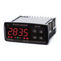
– LoAb = Absolute low alarm: The alarm is activated when
the PV goes below the alarm threshold set at parameter
AL1 and deactivated when the PV goes above the value
[AL1 + HAL1]. With this mode is possible to program, with
AL1L and AL1H parameters, the minimum and the maxi-
mum limits of AL1 thresholds.
– HiAb = Absolute high alarm:
The alarm is activated when the PV goes above the alarm
threshold set at parameter AL1 and is deactivated when
thePV goes below the value [AL1 - HAL1].
In this way is
possible to program, with AL1L and AL1H parameters, the
minimum and the maximum limits of AL1 thresholds.
LoAb
OUT
AL1
PV
HAL1
time
HiAb
offoffoff
OUT
AL1
AL1
PV
HAL1
time
offoffoffON ON ON ON
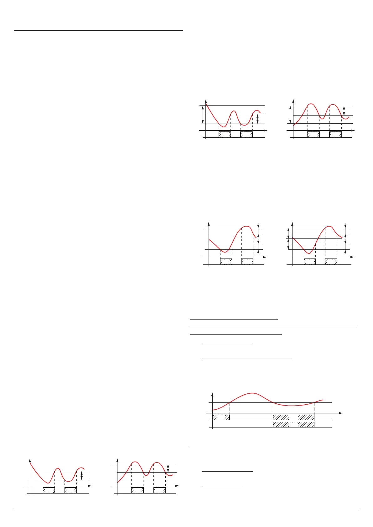
– LodE =
Deviation low alarm: The alarm is activated when
the process value goes below the value [SP + AL1] and is
deactivated when it goes above the value [SP + AL1 + HAL1].
In this way is possible to program, with AL1L and AL1H param-
eters, the minimum and the maximum limits of AL1 thresholds.
– HidE = Deviation high alarm: The alarm is activated when
the process value goes above the value [SP + AL1] and is
deactivated when it goes below the value [SP + AL1 + HAL1].
In this way is possible to program, with AL1L and AL1H param-
eters, the minimum and the maximum limits of AL1 thresholds.
-AL1
Lode
OUT
AL1
SP
AL1
SP
PV
HAL1
time
Hide
offoffoff
OUT
AL1
PV
HAL1
time
offoffoff
ON ON ON ON
– LHAb = Absolute band alarm: The alarm is activated
when the PV goes under the alarm threshold set at pa-
rameter AL1L or goes above the alarm threshold set with
parameter AL1H and is deactivated when the PV returns
inside the range [AL1H - HAL1 ÷ AL1L + HAL1].
– LHdE = Deviation band alarm: The alarm is activated
when the PV goes below the value [SP + AL1L] or above
the value
[SP + AL1H]
and is deactivated when the PV
goes outside the range
[SP + AL1H - HAL1 ÷ SP + AL1L + HAL1].
LHAb
OUT
AL1
AL1L
PV
HAL1
AL1H
-AL1L
AL1H
SP
HAL1
time
LHde
offoffoff
OUT
AL1
PV
time
offoffoff
ON ON ON ON
HAL1
HAL1
Ab1 - Alarm configuration
This parameter can assume a value between 0 and 64.
The number to be set, which will correspond to the function
desired, is obtained by adding the values reported in the fol-
lowing descriptions:
Alarm behaviour at power ON
the alarm output may behave in 2 different ways, depending
on the value added to parameter Ab1.
+0 Normal behaviour: The alarm is always activated when
there are alarm conditions.
+1 Alarm not activated at Power ON: If, at power ON, the
instrument is in alarm condition, the alarm is not activated.
The alarm will be activated only when the Process Palue,
after Power ON, has not been brought into the non-alarm
conditions and subsequently in the alarm conditions.
AL1
PV
time
offoff
Ab1 = +1
Ab1 = +0
offoff
ON ON
ON
Example with absolute low alarm.
Alarm delay
The alarm output may behave in 2 different ways depending
on the value added to parameter Ab1.
+0 Alarm not delayed: The alarm is immediately activated
when the alarm condition occurs.
+2 Alarm delayed: When the alarm condition occurs, delay
counting begins, as programmed at parameter AL1d
(expressed in seconds) and the alarm will be activated