Ascon Tecnologic - K31D - OPERATING INSTRUCTIONS - PAG. 12
sequentially, one of the 2 pre-programmed Set Points;
oFF
Pressing the key for at least 1 s
, is possible to swap
between automatic control (rEG) to OFF control (oFF)
and vice-versa.
5.14 Digital Input
The instrument can be equipped with 2 digital inputs that are
managed by 1 parameter .
The function of the digital input can be set through param-
eter diF contained in the group ]InP.
The parameter can diF be programmed as:
noF No function;
Aac
Closing the contact connected to digital input 1
is pos-
sible to acknowledge the alarm (paragraph 5.11);
ASi
Closing the contact connected to digital input 1 is pos-
sible to acknowledge an active alarm (paragraph 5.11);
HoLd Closing the contact connected to digital input 1 the
istrument holds the measure in that instant (
m
not
the reading on the display, therefore the indication
could settle with a delay proportional to the measure
filter). With the hold function activated, the instrument
operates the control according to the stored measure.
Opening the contact, the instrument returns to the
normal acquisition of the measure;
oFF When the instrument is in rEG state, closing the
contact connected to digital input 1, the instrument is
placed in oFF status. Opening the contact, the instru-
ment returns to the rEG automatic control status;
CHSP
Closing the contact connected to digital input 1
is pos-
sible to select, sequentially, one of the 2 pre-pro-
grammed Set Points;
SP1.2 Closing the contact connected to digital input 1 is pos-
sible to select as active the SP2 Set Point. Opening
the contact the SP1 Set Point is selected as active.
SP1.2 can be selected only when nSP = 2 and, when
active, it disables the selection of the active Set Point
through the parameter SPAt and through the key;
HE.Co Closing the contact connected to digital input 1 is
possible to select as active the Set Point SP2 in CooL
mode. Opening the contact the SP1 Set Point is se-
lected as active in HEAt mode. HE.Co can be selected
only when nSP = 2 and, when active, it disables the
selection of the active Set Point through the parameter
SPAt and through the key.
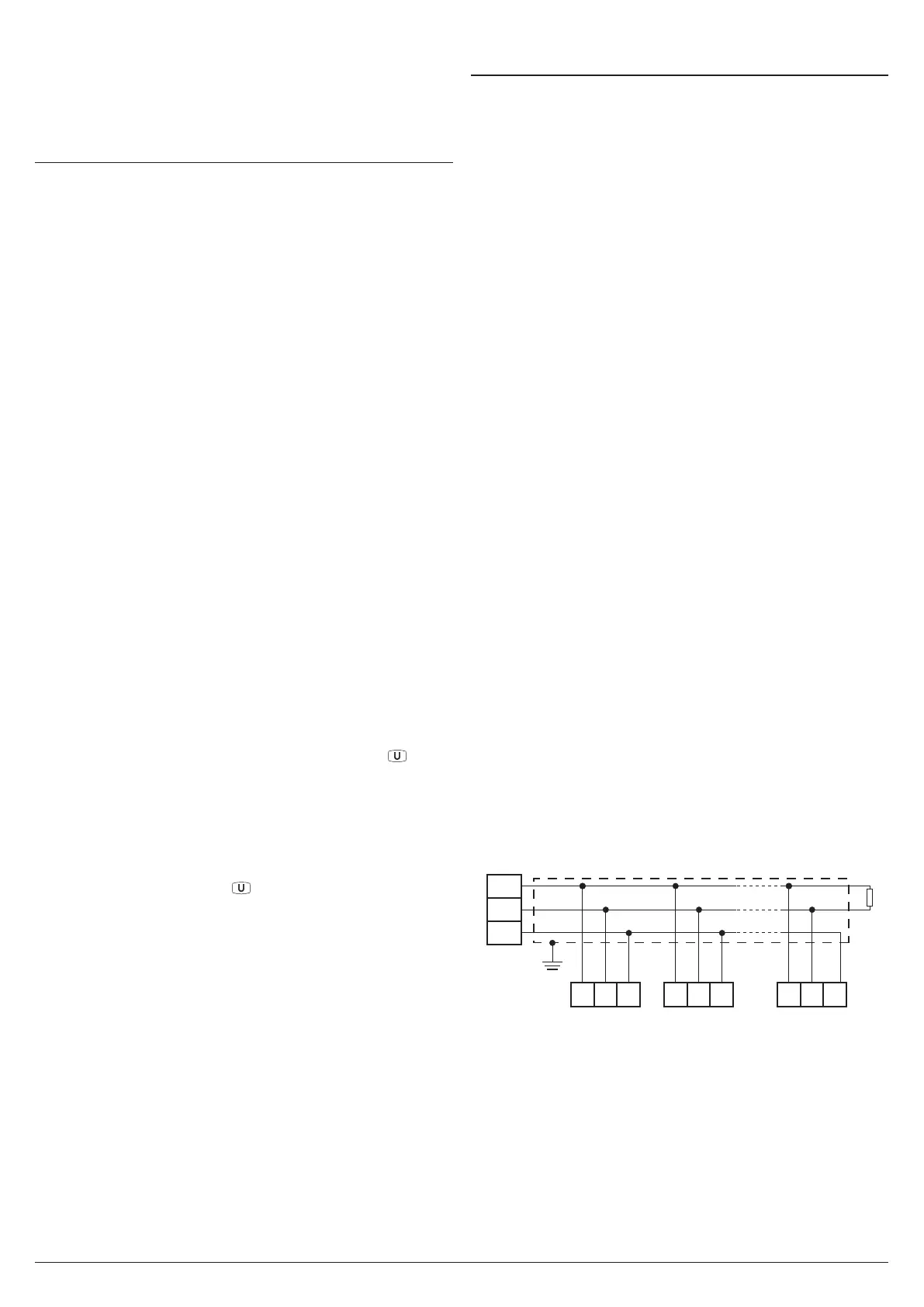
5.15 RS485 Serial Interface
The instrument can be equipped with a RS485 serial com-
munications interface, by means of which it is possible to
connect the controller to a network to which other instru-
ments (PLC controllers) are connected. All these devices
typically depend on a Personal Computer that acts as a
plant supervisor. Using a Personal Computer is possible to
acquire all the function information and to program all the
instrument configuration parameters. The software protocol
adopted for K31D is a MODBUS RTU type, widely used in
several PLC and supervision programs available on the mar-
ket (the manual of the comminications protocol of the K31D
series is available on request).
The interface circuit allows the connection of up to 32 instru-
ments on the same line.
To maintain the line in rest conditions a 120W resistance (Rt)
must be connected to the end of the line.
The instrument has two terminals called A and B that must
be connected to all network terminals with the same label.
For wiring the line, then a twisted pair of telephone type is
sufficient.
However, especially when the network is very long or dis-
turbed, it is advisable to adopt a 3-pole wired and shielded
cable connected as shown.
If the instrument is equipped with a serial interface, the pa-
rameters to be programmed are the following, all present in
the parameters group ]SEr:
Add Address of the station. Set a different number for each
station. Values: 1 ÷ 255.
baud Transmission speed (baud-rate). Values:1200 ÷ 38400
baud. All the stations on the line must have the same
transmission speed.
PACS Programming access. If programmed as LoCL it
means that the instrument is only programmable from
the keyboard, if programmed as LorE it is programma-
ble both from the keyboard and serial line.
If an attempt is made to enter the programming from the
keyboard whilst a communication through the serial port
is in progress the instrument shows the message buSy
to indicate the busy state.
A
B
GND
Host
(OP/PC/PLC)
RS485
Interface
Shield
10
Rt
120Ω
9 8
A GNDB
K31D no. 1
10 9 8
A GNDB
K31D no. 2
10 9 8
A GNDB
K31D no. 31