Ascon Tecnologic - K31D - OPERATING INSTRUCTIONS - PAG. 4
OFF, while any value different from 0 corresponds to
an activated output.
As in the case of automatic control, the programmable
values range from H100 (+100%) to C100 (-100%).
To return to automatic control, select rEG in the selec-
tion menu.
2.5 Active Set Point Selection
This instrument allows to program up to 2 different Set Points
(SP1, SP2) and select which must be considered active.
The number of Set Points is determined by the parameter nSP
located in the
]SP
parameters group.
The active Set Point can be selected:
– By parameter
SPAt
in the group of parameters
]SP
;
– By key
if parameter USrb = CHSP;
– By the digital inputs if parameter diF has been correctly pro-
grammed (diF = CHSP, diF = SP1.2, diF = HE.Co);
– Automatically between
SP1 and SP2
if a time
dur.t
(para-
graph 5.9) has been programmed.
Set Points SP1, SP2 will be visible depending on the maxi-
mum number of Set Points selected with parameter nSP and
they can be programmed with a value that is between the
value programmed in SPLL and the one programmed in SPHL.
Note: In examples that follow the Set Point is indicated as
SP
, however the instrument will act according to the
Set Point selected as active
.
3. USAGE WARNING
3.1 Admitted use
m
The instrument has been projected and manufactured as
a measuring and control device to be used according to
EN61010-1 for the altitudes operation until 2000 ms
.
The use of the instrument for applications not expressly
permitted by the above mentioned rule must adopt all the
necessary protective measures.
The instrument MUST NOT be used in dangerous environments
(flammable or explosive) without adequate protection.
The installer must ensure that EMC rules are respected, also
after the instrument installation, if necessary using proper filters.
4. INSTALLATION WARNINGS
4.1 Mechanical mounting
The instrument, in case 78 x 35 mm, is designed for flush-
in panel mounting. Make a hole 71 x 29 mm and insert the
instrument, fixing it with the provided special brackets.
The instrument can be mounted on panels having a maxi-
mum thickness of 12 mm.
When the maximum front protection (IP65) is desired, the
optional screw type bracket must be used.
Avoid placing the instrument in environments with very high
humidity levels or dirt that may create condensation or cause
the introduction of conductive substances into the instrument.
Ensure adequate ventilation to the instrument and avoid
installation in containers that house devices which may
overheat or which may cause the instrument to function at a
temperature higher than the one permitted and declared.
Connect the instrument as far away as possible from sourc-
es of electromagnetic disturbances such as motors, power
relays, relays, solenoid valves, etc..
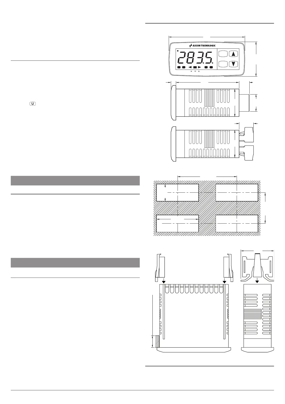
4.2 Dimensions (mm)
4.2.1 Mechanical dimensions
K31D
Tun
Out1 Out2 Out3 Out4
P
U
18.5
2828
12
14.5
5.5 64
78
35
4.2.2 Panel cut-out
41 min.
71
+0.6
29
+0.6
4.2.3 Brackets
Panel thickness: 12 mm max.
Brackets
4.3 Electrical connections
Carry out the electrical wiring by connecting only one wire to
each terminal, according to the following diagram, checking
that the power supply is the same as that indicated on the