Ascon Tecnologic - K31D - OPERATING INSTRUCTIONS - PAG. 19
9.3 Functional Features
Control: ON/OFF, Neutral zone, single and double action PID;
Measurement range:
Probe type dP = 0 dP = 1
PTC (KTY81-121) SEnS = Ptc
-55 ÷ +150°C
-67 ÷ +302°F
-55.0 ÷ +150.0°C
-67.0 ÷ +302.0°F
NTC (103-AT2) SEnS = ntc
-50 ÷ +110°C
-58 ÷ +230°F
-50.0 ÷ +110.0°C
-58.0 ÷ +230.0°F
Pt1000 SEnS = Pt10
-50 ÷ +350°C
-58 ÷ +662°F
-50.0 ÷ +350.0°C
-58.0 ÷ +662.0°F
Display resolution: According to the probe used 1°/0.1°;
Overall accuracy: ±(0.5% fs + 1 digit);
Sampling rate: 130 ms;
Serial Interface: Isolated RS485;
Communications protocol: MODBUS RTU (JBUS);
Baud rate: Between 1200
÷
38400 baud;
Display: 4 Digit Red h 12 mm;
Compliance: ECC directive EMC 2004/108/CE (EN 61326),
ECC directive LV 2006/95/CE (EN 61010-1).
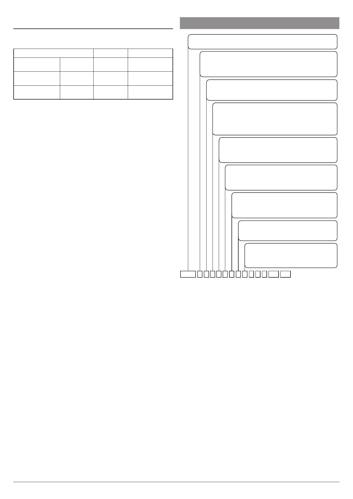
10. HOW TO ORDER
Model
K31D = Instrument with mechanical keys
a: Power supply
H = 100... 240 VAC
L = 24 VAC/DC
F = 12 VAC/DC
b: Inputs
2 = For PTC, NTC Thermistors or
Pt1000 resistance thermometer
d: Output 2 (Out2)
R = Relay SPDT 8A (resistive load)
O =
Vdc for SSR
- = Not present
e: Output 3 (Out3)
R = Relay SPST-NO 5A (resistive load)
O =
Vdc for SSR
- = Not present
f: Output 4 (Out4)
R = Relay SPST-NO 5A (resistive load)
O =
Vdc for SSR
- = Not present
c: Output 1 (Out1)
R = Relay SPDT 8A (resistive load)
O = Vdc for SSR
I = Analogue Output 0/4...20 mA; 0/2...10 V
(only with L tye power supply and without RS485)
g: Communications Interface
S =
RS 485 Serial interface
- = Not present
h: Connector Terminals
- = Screw terminals (standard)
E = Removable socket with screw
terminals
caK31D b-e- -hi ll mmj
i, j, k: RESERVED CODES;
ll, mm: SPECIAL CODES.
k
Note: To order the screw type bracket necessary to obtain
the IP65 protection degree, contact our sales offices.