Ascon Tecnologic - K31D - OPERATING INSTRUCTIONS - PAG. 7
5.5 Neutral Zone ON/OFF Control (1.rEG - 2.rEG)
All the parameters referring to Neutral Zone ON/OFF control
are contained in the group ]rEG.
This type of control can be obtained when 2 outputs are pro-
grammed respectively as 1.rEG and 2.rEG and the parameter
Cont = nr.
The Neutral Zone control is used to control plants in which
there is an element which causes a positive increase (e.g.
Heater, humidifier, etc.) and an element which causes a
negative increase (e.g. Cooler, de-humidifier, etc.).
The control functions work on the programmed outputs de-
pending on the Process Value (PV), the active Set Point SP
and the HSEt hysteresis.
The control works in the following way: deactivates the out-
puts when the PV reaches the Set Point and it activates
the output 1.rEG when the PV goes below the [SP - HSEt]
value, or activates the output 2.rEG when the PV goes
above the [SP + HSEt] value.
Consequently, the element causing a positive increase
must be connected to the output programmed as 1.rEG
while the element causing a negative increase must be
connected to the output programmed as 2.rEG.
HSEt
HSEt
SP
PV
time
Out 1.rEG
(heating)
Out 2.rEG
(cooling)
offoff
off
ON
ON
ON
If 2.rEG output is used to control a compressor, it is possi-
ble to use the “Compressor Protection” function that is used
to avoid compressor “short cycles”. This function allows a
time control on 2.rEG output activation, regardless of the
temperature control requests. The protection is a “delayed
after deactivation” type.
This protection avoids the output activation for a time
programmable at parameter CPdt (in seconds); the output
activation occurs only after the CPdt time has elapsed.
The CPdt protection time count starts from the last 2.rEG
output deactivation.
Obviously, whether during the time delay caused by the com-
pressor protection function, the control request should stop, the
output activation foreseen after time CPdt would be erased.
The function is deactivated by programming CPdt = OFF.
The LED relative to 2.rEG output 2 blinks during the output ac-
tivation delay, caused by the “Compressor Protection” function.
5.6 Single Action PID Control (1.rEG)
All the parameters referring to PID control are in ]rEG group.
The Single Action PID control can be obtained by program-
ming parameter Cont = Pid and works on 1.rEG output depend-
ing on: the active Set Point SP, the functioning mode Func and
on the instrument PID algorithm with 2 freedom degrees.
If the Out1 analogue output is present (0/4 ÷ 20 mA; 0/2 ÷ 10 V)
the output will operate as a regulation output providing a
value proportional to the regulation power calculated by the
instrument.
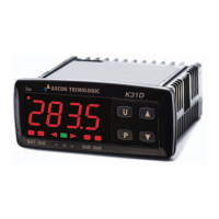
PV
SP
100%
0%
time
ON ON ON ON ON ON ON
off off off off off off off
Digital
OUT1
1.rEG
(HEat)
Analogue
OUT1
1.rEG
(HEat)
tcr1tcr1 tcr1 tcr1 tcr1 tcr1 tcr1
In presence of fast processes, in order to obtain a good PV
stability, the tcr1 cycle time must have a low value with a
very frequent intervention of the control output. In this case
we recommend to use a Solid State Relay (SSR) for driving
the actuator.
The Single Action PID control algorithm foresees the setting of
the following parameters
:
Pb Proportional Band;
tcr1 Cycle time of 1.rEG output;
Int Integral Time;
rS Manual Reset (only if Int = 0);
dEr Derivative Time;
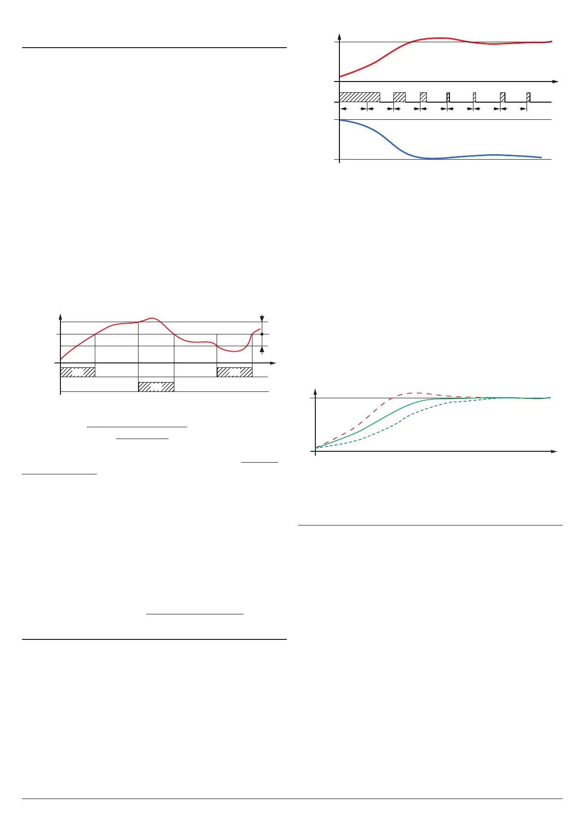
FuoC Fuzzy Overshoot Control.
This last parameter allows the variable overshoots at the start up
of the process or at the changing of the Set Point to be avoided.
Please remember that a low value on this parameter reduces
the overshoot while a high value increase it.
PV
SP
time
1
3
1 FuoC Value OK;
2 FuoC Value too high;
3 FuoC Value too low.
5.7 Double Action PID Control (1.rEG - 2.rEG)
All the parameters referring to PID control are in ]rEG group.
Double Action PID control is used to control plants where
there is an element which causes a positive temperature in-
creases (ex. Heating) and an element which causes a nega-
tive temperature increases (ex. Cooling) and can be obtained
when 2 outputs are programmed respectively as 1.rEG and
2.rEG and setting Cont = Pid.
The element causing the positive increase must be con-
nected to the output programmed as 1.rEG while the element
causing the negative increase must be connected to the
output programmed as 2.rEG.
The Double Action PID control works on the outputs 1.rEG
and 2.rEG depending on the active Set Point SP and on the
instrument’s PID algorithm with 2 freedom degrees.
In presence of fast processes, in order to obtain a good Process
Variable stability, cycle times tcr1 and tcr2 must have a low
value with a very frequent intervention of the control outputs.
In this case we recommend to use Solid State Relays (SSR)
for driving the actuators.