Ascon Tecnologic - K31D - OPERATING INSTRUCTIONS - PAG. 11
only after that time has elapsed.
AL1
PV
time
offoff
Ab1 = +2
Ab1 = +0
offoffoff
ON
ON
ON
AL1d AL1d
ON
Example with absolute low alarm.
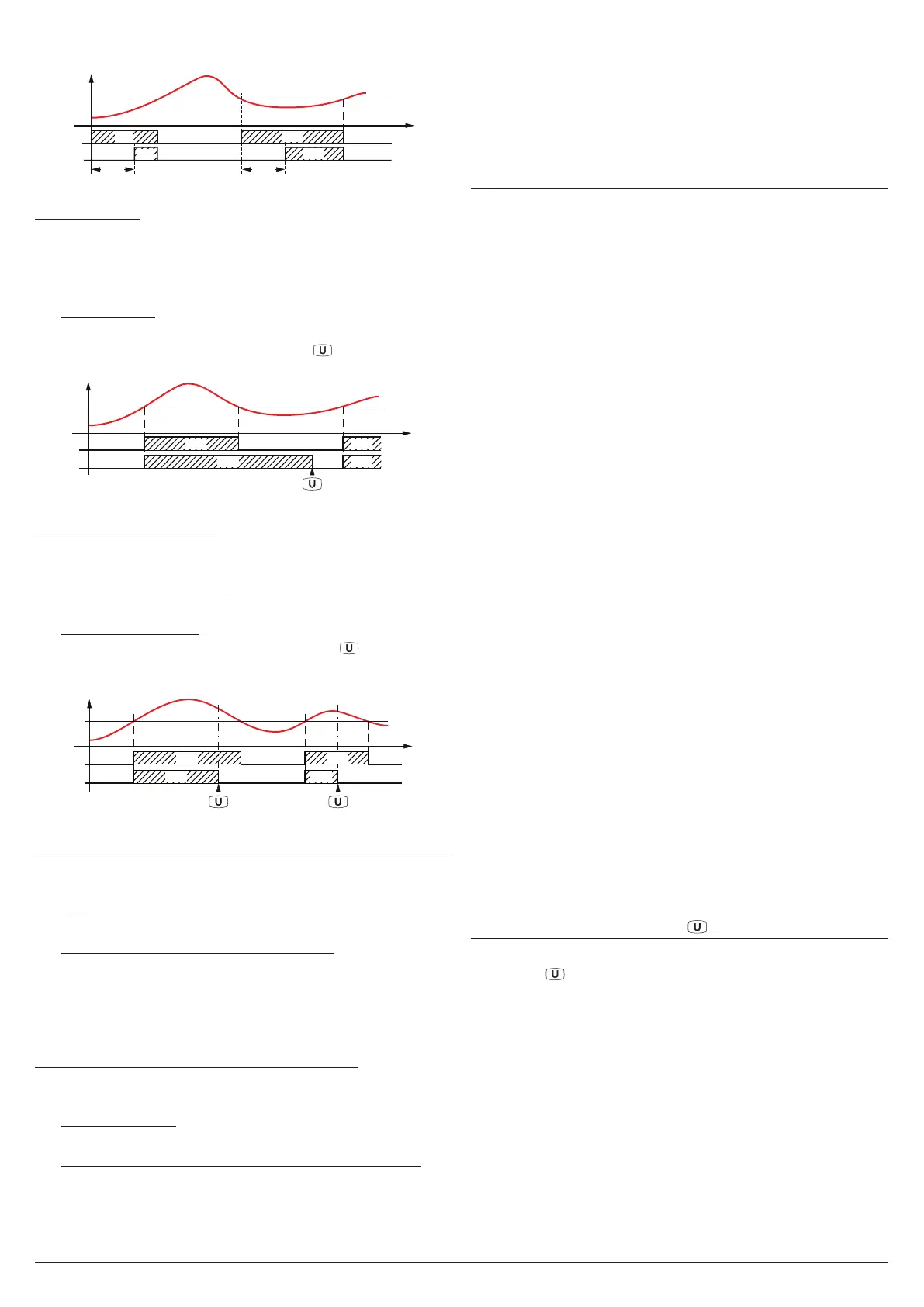
Latched alarm
The alarm output may behave in 2 different ways depending
on the value added to parameter Ab1.
+0 Alarm not latched: The alarm remains active in alarm
conditions only.
+4
Latched alarm: The alarm is active in alarm conditions and
remains active even when these conditions no longer exist,
until the correctly programmed key , (USrb = Aac) is
pressed or is closed the Digital Input (diF = Aac).
AL1
PV
time
offoff
Ab1 = +4
Ab1 = +0
ON ON
or Digital Input
offoff
ON ON
Example with absolute high alarm.
Alarm acknowledgement
The alarm output may behave in 2 different ways depending
on the value added to parameter Ab1.
+0 Alarm not acknowledged: The alarm remains active in
alarm conditions only.
+8
Alarm acknowledged: The alarm is active in alarm condi-
tions and can be deactivated pressing the
key (if prop-
erly programmed: USrb = ASi) or is closed the Digital Input
(diF = Aac) also if the alarm conditions are still present.
AL1
PV
time
off
Ab1 = +8
Ab1 = +0
off
offoff
offoff
ON
ON ON
ON
or Dig. Input or Dig. Input
Example with absolute high alarm.
Alarm behaviour at Set Point change (deviation alarms only)
the alarm output may behave in 2 different ways, depending
on the value added to parameter Ab1.
+0 Normal behaviour: The alarm is always activated when
there are alarm conditions.
+16 Alarm not activated at Set Point change: In case of a Set
Point change, if the instrument is in alarm condition, the
alarm is not activated. The alarm will be activated only
when the process value, after Set Point change, has not
been brought into the non-alarm conditions and subse-
quently in the alarm conditions.
Control output shutdown whith alarm active
There are 2 different alarm output behaviors, depending on
the value added to Ab1.
+0 Normal behavior: The alarm does not affect the control
output.
+32 Control output shutdown when the alarm is triggered:
When the instrument detects the activation of the alarm
status, disables the control output. The output is reac-
tivated on the basis of the previously selected alarm
options (acknowledgment of alarms, etc.).
AL1i -
Alarm activation in case of measurement error
This parameter allows to establish how the alarm must be-
have in the event of a measurement error:
yES Alarm active;
no Alarm deactivated.
5.12 Loop Break Alarm Function
All the parameters referring to the Loop Break alarm function
are contained in the group ]LbA.
The Loop Break alarm is available on all the instruments,
which intervenes when, for any reason (short-circuit of a
thermocouple, thermocouple inversion, load interruption),
the loop control is interrupted.
First of all, it is necessary to establish to which output the
alarm must be addressed.
To do this it is necessary to set, in the group ]out, the param-
eter relative to the output to be used (o1F, o2F, o3F, o4F)
programming the parameters as:
ALno If the alarm output must be ON when the alarm is ac-
tive while it is OFF when the alarm is not active;
ALnc If the alarm output must be OFF when the alarm is
active while it is ON when the alarm is not active;
ALni
The same behaviour as
ALnc
but with a reversed LED
indication (the LED indicates the output status).
Enter group ]Lba and program, with parameter oLbA, to
which output the alarm signal must be addressed.
The Loop Break alarm is activated if the output power
remains at the 100% for the time programmed at parameter
LbAt (expressed in s).
To avoid unwanted alarms, the value of this parameter must
be set considering the time the plant takes to reach the Set
Point when the measured value is far from it (for example at
plant start-up).
When the alarm is triggered, the instrument displays the
message LbA and behaves as in the case of a measurement
error giving a power output as programmed with parameter
OPE (group ]InP).
To restore normal functioning after the alarm intervention,
select the control mode oFF and then reprogram the auto-
matic control (rEG) after checking the correct functioning of
probe and actuator.
In order to exclude the Loop Break alarm, set:
OLbA OFF.
5.13 Functioning of Key
In addition to the normal display function of Pr1, Pr2 and
P1 - 2, the key can be programmed to perform other func-
tions using the USrb parameter contained in the ]PAn group.
The parameter USrb can be programmed as:
noF No function;
tunE
Pressing the key for at least 1 s, is possible to activate/
deactivate Auto-tuning or Self-tuning (if programmed)
oPLo
Pressing the key for at least 1 s
, it is possible to swap
from automatic control (rEG) to manual one (oPLo)
and vice-versa;
Aac
Pressing the key for at least 1 s
, is possible to acknowl-
edge the alarm (paragraph 5.11);
ASi
Pressing the key for at least 1 s
, is possible to acknowl-
edge an active alarm (paragraph 5.11);
CHSP
Pressing the key for at least 1 s
, is possible to select,