RRM02 - Product Manual
Issue: 02 complete, approved
Page 22 of 68
4.3 Connection to ASL PA/VA Systems
4.3.1 Connection of a Single RRM02 Unit
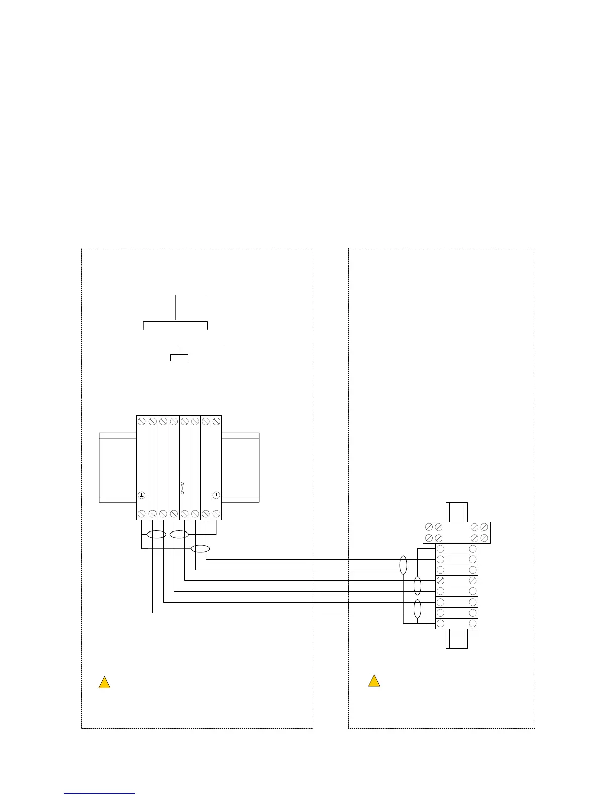
4.3.1.1 Serial Data and Audio Connection to a VAR Router Microphone Input
Figure 15 shows an example of DIN rail terminal layout and connection to the equipment rack where the
VAR Router is installed. Note that the actual DIN rail and terminal position in the rack depends on the rack
specific design, cable entry direction, etc.
Refer to Section “3.2.2.1 Cabling for Serial Data and Audio Connection to an ASL VAR Router, DAU, or ACU
Microphone Input” (page 9) for recommended cabling.
Figure 15 Connection to the VAR Router (Example)
RRM02 ENCLOSURE
CABLE SCREEN TAILS TO BE < 3 cm.
!
!
CABLE ENDS TO BE FITTED WITH SUITABLE
BOOTLACE FERRULES.
L
CENTRAL EQUIPMENT RACK
T0.5A
MIC AUDIO IN-
SCREEN
DXN
DXP
+V SUPPLY
0V SUPPLY
SCREEN
MIC AUDIO IN+
VAR4 INPUT 1-4
VAR8 INPUT 1-8
VAR8-ACU INPUT 1-8
VAR12 INPUT 1-12
VAR20 INPUT 1-20
SHIELD
AUDIO+
AUDIO-
0V
+V
DXP
DXN6
5
4
3
2
1
SHIELD
(No user
connection)
654321
CABLE SCREEN TAILS TO BE < 3 cm.
!
!
CABLE ENDS TO BE FITTED WITH
SUITABLE BOOTLACE FERRULES.
L
18 - 40 V
(NOT the power supply
from the Router input)
7
RELAY