RRM02 - Product Manual
Issue: 02 complete, approved
Page 55 of 68
8.2 Radio Microphone Receiver Adjustments and Monitoring
The following procedure describes how to modify the Radio Microphone Receiver settings after installation.
The Radio Microphone Receiver also provides indication of the received RF signal level.
Adjusting and Monitoring the Radio Microphone Receiver:
1. Remove the lid of the unit by unscrewing the four corner fixings.
2. Power the unit off as described in Section “8.1 Powering the RRM02 On and Off” (page 54).
3. The controls required in the following configurations are shown in Figure 22 (page 32):
a. If required, select the new Receiver Channel RF frequency via the internal rotary switch.
Refer to Section “5.1 Radio Microphone Receiver Frequency Selection” (page 33) for frequency
configuration.
b. If required, enable or disable the pilot tone detection by setting DIP switch 1 on the microphone
PCB.
Refer to Section “5.2 Radio Microphone Receiver Pilot Tone Detection Configuration” (page 34)
for pilot tone detection configuration.
c. If required, select the squelch level by setting DIP switches 3 and 4 on the microphone PCB.
Refer to Section “5.3 Radio Microphone Receiver Squelch Level Configuration” (page 35) for
squelch level configuration.
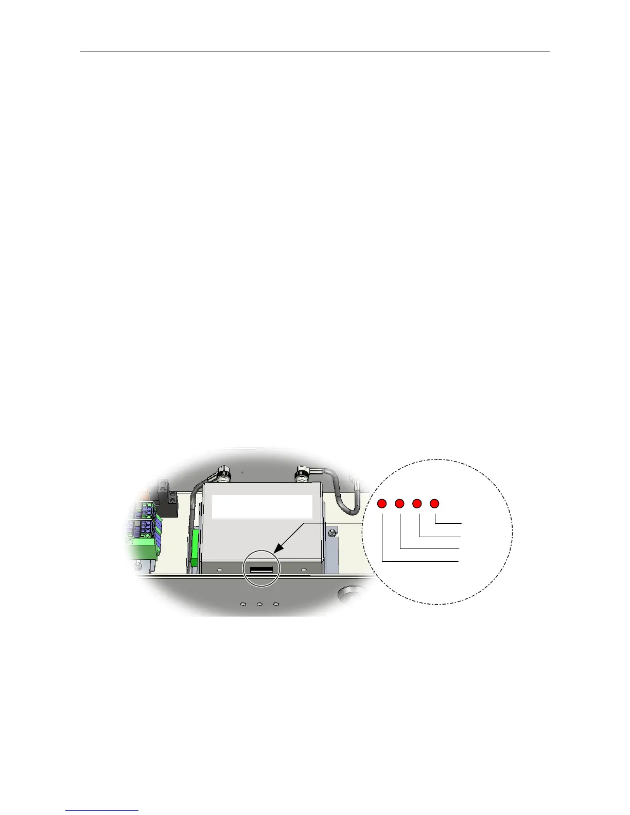
4. If required, the strength of the received RF signal can also be monitored from indicators provided on
the lower face of the Radio Microphone Receiver (see Figure 26).
Figure 26 Radio Microphone Receiver RF Level Indicators
RADIO MICROPHONE
RECEIVER
-74 dBm
-79 dBm
-86 dBm
-93 dBm
5. When finished, power the unit on as described in Section “8.1 Powering the RRM02 On and Off”
(page 54).
6. Fix the lid back in position, screwing it tight to provide an IP65 seal, but not excessively tight so that
any of the fixing threads are stressed, as this may cause them to weaken and shear.