RRM02 - Product Manual
Issue: 02 complete, approved
Page 7 of 68
3 Installation
3.1 Main Components
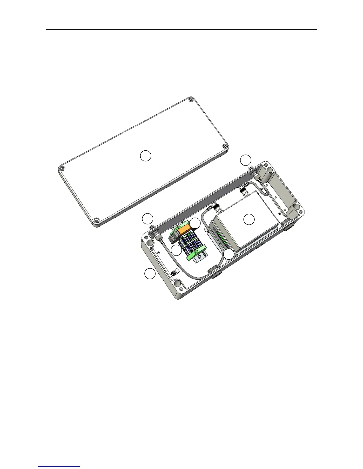
Figure 1 Main Components
1
5
3
4
6
7
2
2
(LOWER FACE)
(Internal wiring omitted for clarity.)
1
Cast aluminium lid
2
Antenna connections:
TNC connectors for antenna connection direct to the upper face of the unit. Pre-fitted adaptor
leads provide internal connection to the Radio Microphone Receiver.
L Cable entry holes are provided on the lower face of the unit as alternative antenna cable
entry points; refer to Section “3.2.2.3 Antenna Cabling” (page 10) for connection details.
3
Radio Microphone Receiver
4
Microphone PCB underneath and protected by a metal bracket
5
Cast aluminium box
6
DIN rail terminals for field cabling
7
Relay for interfacing to other manufacturer’s PA systems, and for connection of multiple RRM02
units