RRM02 - Product Manual
Issue: 02 complete, approved
Page 35 of 68
5.3 Radio Microphone Receiver Squelch Level Configuration
The squelch level switch sets the minimum RF signal strength that can be received. This is set to a level that
receives the Radio Microphone transmissions, while rejecting external interference.
If there is any interference then the squelch level should be set to the least sensitive setting in order to
minimise interference. However if this causes the Radio Microphone transmissions to not be received then it
can be made more sensitive in steps until the Radio Microphone transmissions are received correctly.
The squelch level is set by DIP switches 3 and 4 located on the microphone PCB (see Figure 22, page 32),
with the future option of setting it by the Router configuration.
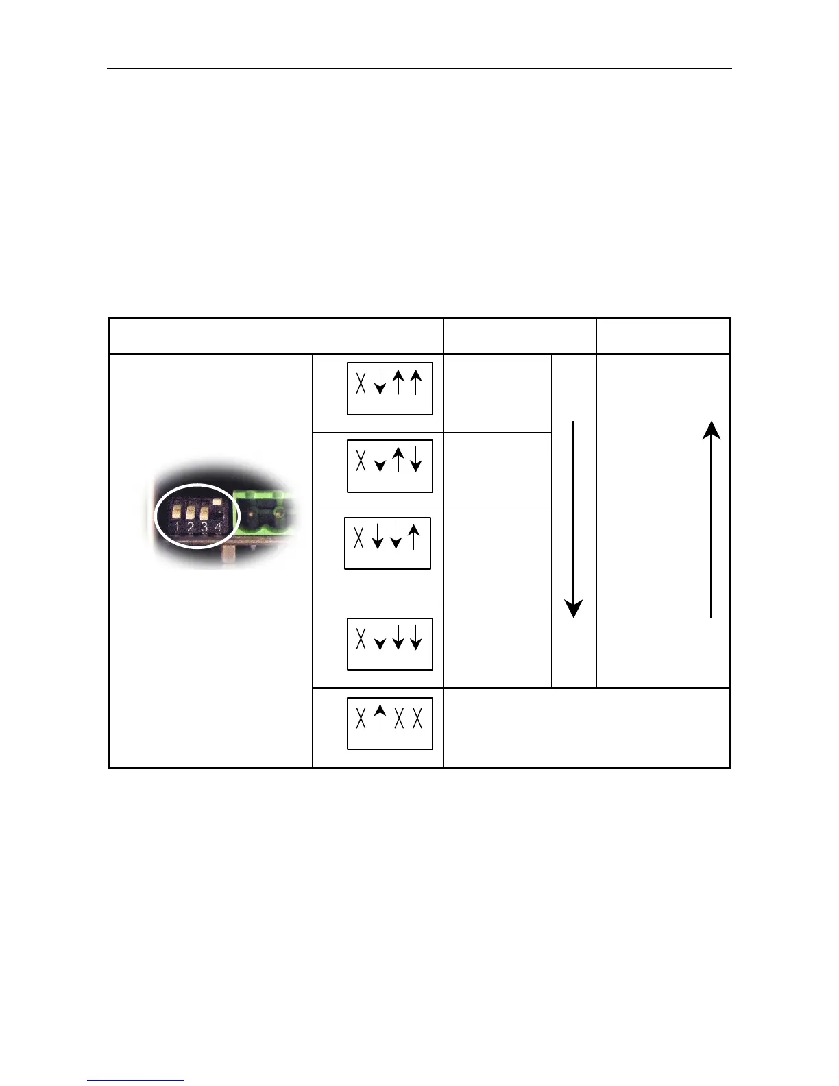
Table 4 Radio Microphone Receiver Squelch Level Selection
DIP Switch Positions Receiver Squelch Level
Received RF Signal
Strength
1 2 3 4
ON
Least sensitive
–76 dBm
Strong signal
required
1 2 3 4
ON
–86 dBm
1 2 3 4
ON
(Factory default)
–93 dBm
1 2 3 4
ON
Most sensitive
–99 dBm
Weak signals
received
(Factory default)
È
ON
1 2 3 4
ON
For future use.
This switch position will be used to set the squelch
level, the pilot tone detection, and the frequency
selection to be controlled through the Router
configuration.