RRM02 - Product Manual
Issue: 02 complete, approved
Page 33 of 68
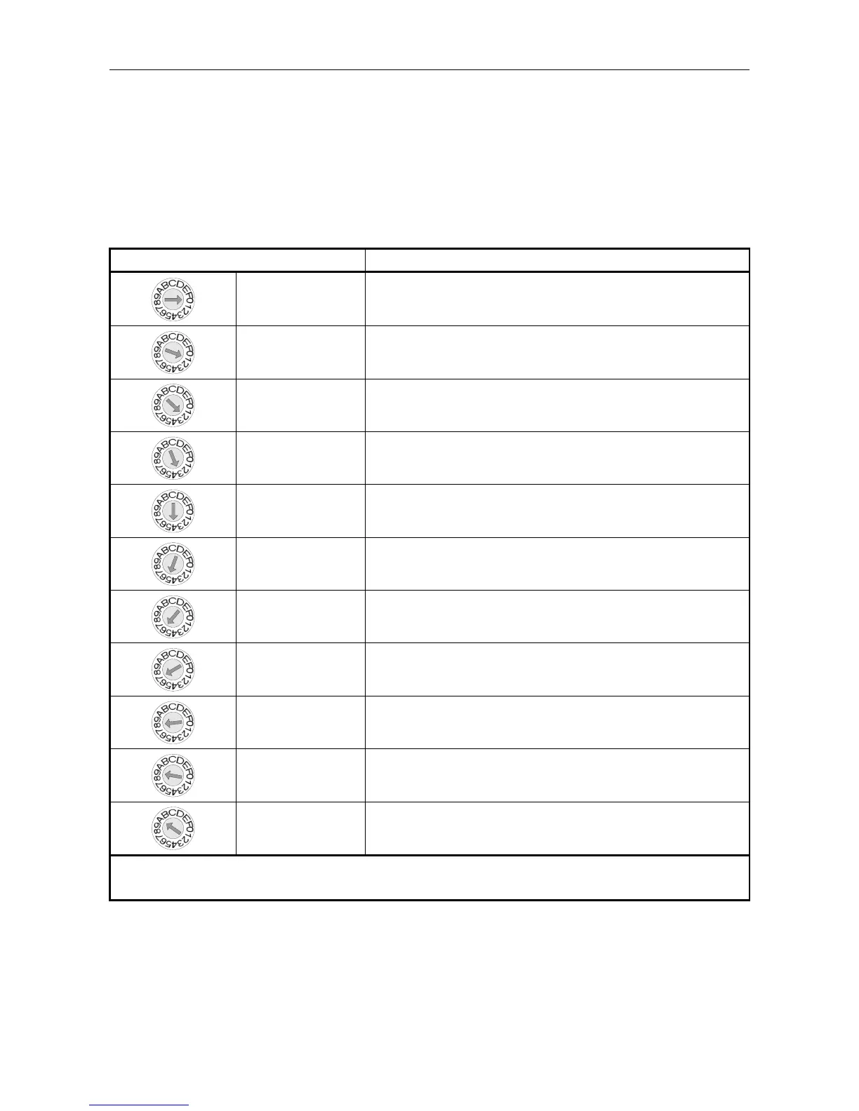
5.1 Radio Microphone Receiver Frequency Selection
The Receiver frequency is selected using the rotary switch; with the future option of setting it by the Router
configuration by positioning the DIP switch 2 as described in Table 3 (page 34) and Table 4 (page 35).
The switch is located on the upper face of the Radio Microphone Receiver module inside the RRM02, as
shown in Figure 22 (page 32).
Table 2 Radio Microphone Receiver Frequency Selection
Frequency Selection Switch Position Corresponding Radio Microphone Transmitter Channel Number
0 1
1 2
2 3
3 4
4 5
5 6
6 7
7 8
8 9
9 10
A to F 10
L Frequencies in the Channel 70 license free band. Available from Application Solutions (Safety and Security)
Limited on request.