20
R
TECHNICAL DATA ENGLISH
Operating voltage: 12 (-10%) – 24 (+15%) V DC STAB
Current: 12 V DC Max. 550 mA
Idle 240 mA
24 V DC Max. 270 mA
Idle 110 mA
Micro switch: Max. 0.4 A 30 V AC/V DC resist, 10 W
Ambient temperature: -20° - +60° C
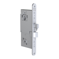
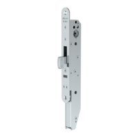
Bolt throw: 14 mm / 20 mm (EL580, EL582)
14 mm (PE580)
Backset: 50 mm
70 mm
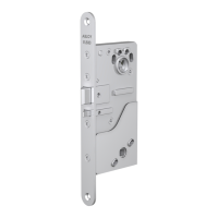
Forend: 22 mm
Spindle: 8 mm
Split spindle: 57 / 50 mm (EA288 002000) (Table I) (EL580, PE580)
Functions selected on the lock case:
Mechanical functions
-opening directions of trigger bolt and latch bolt
-bolt throw (14 mm / 20 mm EL580, EL582)
-controlled side (EL580, PE580)
Electrical function
-power on -> controlled handle opens the lock
or
-power on -> controlled handle does not open the lock
The lock can always be opened with the handle on the active
side (EL580, PE580).
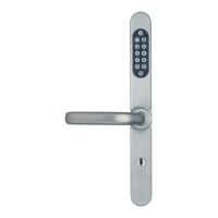
Indications: -deadlock status of latch bolt
-indication of handle operation
Door gab: 3 – 5 mm (between forend and strike plate)
Connection cable: EA210 (6 m), EA220 (10 m) 18 x 0.14 mm2
Strike plate: LP712/LP717/LP722/LP732 (4630/4631/LP701)
Use handles with return springs on both sides of the door.
In fi re doors please use 14mm bolt throw (factory setting 20 mm).
TESTED ACCORDING TO THE STANDARDS
EN STANDARDS
EN 179: 1997 / Al: 2001 3 7 6 1 1 3 4 2 A Exit (EL580)
EN 1125: 1997 / Al: 2001 3 7 6 1 1 3 3 2 A Panic exit (PE580)
EN 1634-1 Fire
EN 61000-6-1: 2001 EMC
EN 61000-6-3: 2001 EMC
EN 12209: 2004 Mechanical strength
!
!
 Loading...