21
R
!
!
EMERGENCY EXIT DEVICES INSTALLATION ACCORDING TO EN 179
The following lock cases and handles are approved to be installed together in an emergency
exit door. Strike plate LP712/LP717/LP722/LP732 must be used in the installation.
Maximum door size: height 2520 mm, width 1320 mm, mass 200 kg.
The lock can always be opened mechanically inside by exit handle and outside by key.
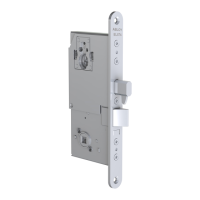
Lock case ABLOY® handle
EL580 3-20/007 3-20/002 3-19/002 13/032O 13/032V
Functional check after installation:
Emergency exit (active) side and functional sensitivity tests:
- Use exit handle. Exit handle is correctly set if the latch bolt goes inside the lock case irre-
spective of electrical control.
- Opening force by exit handle is about 30 N (approximately 3 kg weight at a 100 mm dis-
tance from the handle pivot opens the lock). According to EN 179 the force must be less
than 70 N.
- Close the door slowly and check that the latch bolt deadlocks.
- Check that the latch bolt slides freely into the strike plate.
The safety features of this product are essential to its compliance with EN 179. No
modifi cation of any kind, other than those described in these instrictions, are permit-
ted
PANIC EXIT DEVICES INSTALLATION ACCORDING TO EN 1125
The following lock cases and push bars are approved to be installed together in a panic exit
door. Strike plate LP712/LP717/LP722/LP732 must be used in the installation.
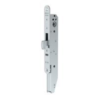
Lock case ABLOY® push bar
PE580 PBE001
Functional check after installation:
Panic exit (active)side and functional sensitivity tests:
- Push the push bar towards the door on the exit side. Exit side is correctly set if the bolt
goes inside the lock case irrespective of the electrical control.
- Force to open the lock by pushing the push bar is about 60 N with no pressure on door
(approximately 6 kg weight tested in three different points, see picture above). According to
EN 1125 it must be less than 80 N.
- Close the door slowly and check that the lock deadlocks.
- Check that the bolts slide freely into the strike plate.
Note! The length of the push bar must be at least 60 % of the width of the door.
The safety features of this product are essential to its compliance with EN 1125. No
modifi cation of any kind, other than those described in these instrictions, are permit-
ted.
Recommended distance from a fl oor to a handle or to a push bar is between
900mm - 1100mm.
Lubricate the bolts of the lock case at least once a year. Use vaseline type lubrication
(e.g. ISOFLEX TOPAS NB52).
Note! Abloy Oy will not be liable for products in case these instructions are not followed.
25mm 25mm
 Loading...