23
R
MANIPULATION PROTECTION COVER Fig. A ENGLISH
1. Bend the corner of manipulation protection cover a little and
2. move the cover away.
3. Before putting the manipulation protection cover back in its place, bend lightly the sides of
the cover together.
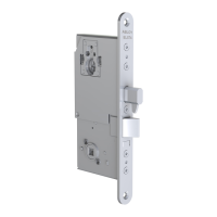
CHANGING THE DIRECTION OF THE SOLENOID ACTION Fig. B, Fig. C, Fig. D
1. Unscrew the fi xing screw and pull out the changer.
2. Turn the changer round as shown in the fi gure A.
3. Put the changer back and screw in the fi xing screw. Make sure the changer is straight and
fi ts tightly in the lock case.
Please ensure that the long pin on the changer locates in the hole of the white nylon bush.
When the arrows on the changer and on the lock case are positioned as shown in fi gure C,
the lock is set on fail locked mode:
- power on -> the controlled handle will open the lock
- power off -> the controlled handle will not open the lock
When the arrows on the changer and on the lock case are positioned as shown in fi gure D,
the lock is set on fail unlocked mode:
- power on -> the controlled handle will not open the lock
- power off ->, the controlled handle will open the lock
CHANGING THE OPENING DIRECTION OF THE TRIGGER BOLT Fig. E
Need tool: 2 mm Allen key
1. Loosen the fi xing screw of the trigger bolt.
2. Pull the trigger bolt out and turn it round.
3. Put the trigger bolt back to place.
4. Tighten the fi xing screw.
CHANGING THE OPENING DIRECTION OF THE LATCH BOLT Fig. E
Need tool: 2.5 mm Allen key
5. Check that the latch bolt is not deadlocked.
6. Unscrew the fi xing screw of the latch bolt.
7. Pull the latch bolt out and turn it round.
8. Put the latch bolt back in place.
9. Tighten the fi xing screw to the other side of the lock case.
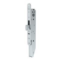
CHANGING THE BOLT THROW (EL580, EL582) Fig. F, Fig. G
Tool: 2.5 mm Allen key
Bolt throw change from 20 mm to 14 mm:
1. Check that the bolt is not deadlocked.
2. Remove the latch bolt fi xing screw.
3. Push the trigger bolt in and at the same time push the latch bolt in momentarily.
4. Check that the tailpiece is in deadlocked position.
5. Tighten the latch bolt fi xing screw .
6. Check the function of the bolt.
!
 Loading...