22
R
!
WIRING DIAGRAM ENGLISH
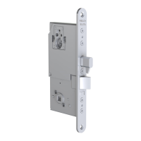
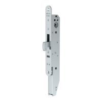
ABLOY® EL580, EL582, PE580 SOLENOID LOCK
LOCK CASE INCLUDES PROTECTION DIODES.
EXTENSION CABLE EA210/EA220.
MAXIMUM VALUES FOR MICRO SWITCHES:
0.4 A 30 V AC RESIST; 0.4 A 30 V DC RESIST; MAX. 10 W
NO VALUE SHOULD BE EXCEEDED.
NO = Handle down
C = Common
NC = Handle not down
brown
orange
grey
12 (-10%) - 24 (+15%) V DC STAB
C = Common
NC = Bolt deadlocked
NO = Bolt not deadlocked
OPEN/LOCKED
red
black
yellow
blue
green
WARNING:
Do not use handle down indication to
lock’s control. *)
*) It is made for access control and prevention of the burglary alarm. In some burglary alarm
systems prevention of the alarm and lock’s control are working at the same time. If you can not
separate these functions, it is not allowed use handle down indication to prevention of the bur-
glary alarm. That might cause unauthorized entrance.
 Loading...