7
ML2000 Series Mortise Lock
Installation Instructions
Used with VN Escutcheon Trim and V Series Indicators
FM521 08/19
Copyright © 2019, ASSA ABLOY Access and Egress Hardware Group, Inc. All rights reserved. Reproduction in whole or
in part without the express written permission of ASSA ABLOY Access and Egress Hardware Group, Inc. is prohibited.
For installation assistance contact Corbin Russwin
1-800-543-3658 • techsupport.corbinrusswin@assaabloy.com
5 Installation Instructions (cont.)
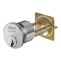
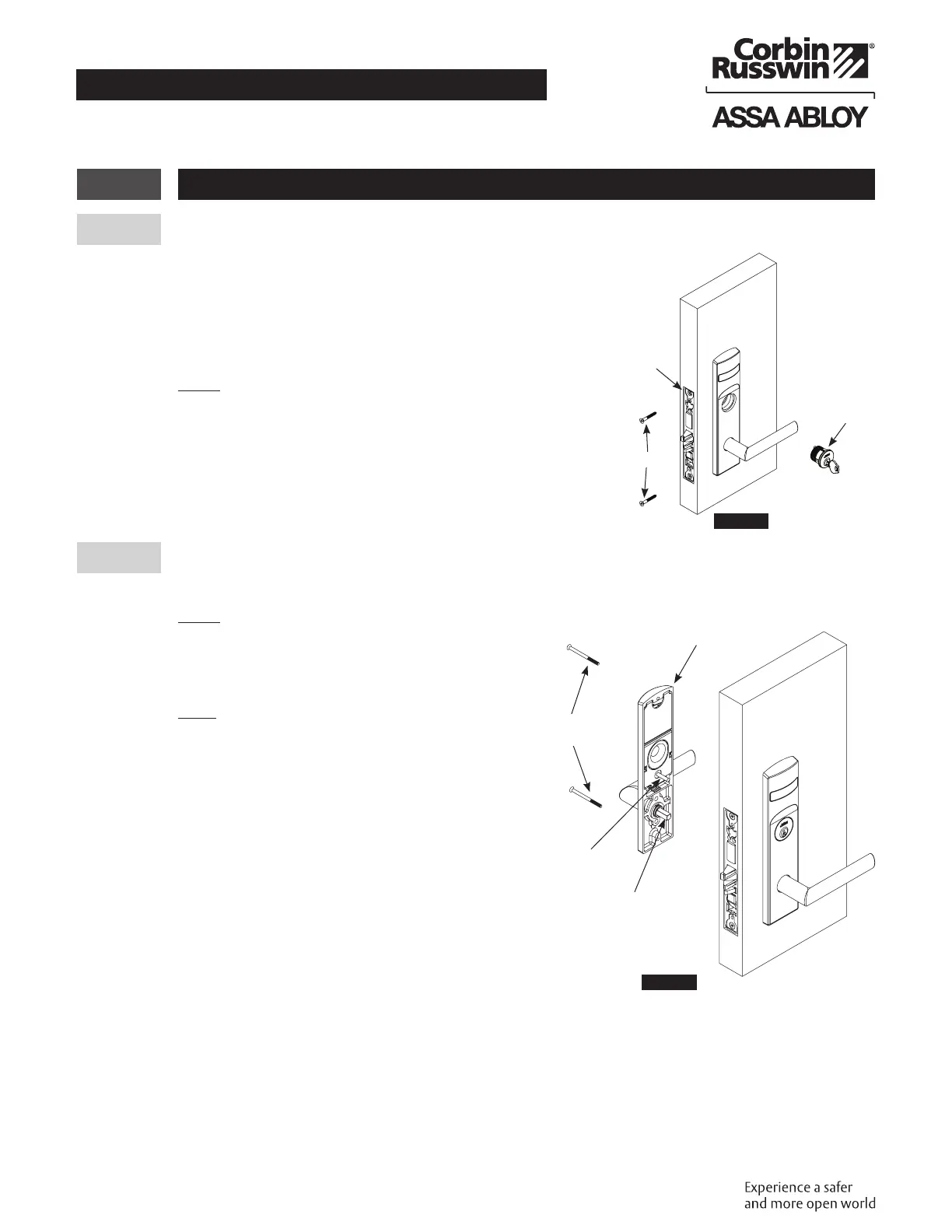
d Install Cylinder
1. Thread cylinder into lock until flush with surface.
2. Install the cylinder clamp screw (#2 Phillips screwdriver).
3. Check operation, and adjust cylinder if necessary.
4. Secure lock in door with two (2) Combination screws
Do NOT tighten completely at this time. (Figure12)
NOTE:
• CORBIN RUSSWIN logo must be horizontal and on top
portion of cylinder.
• Designed for 1-1/8" cylinders. For longer cylinders consult
factory.
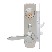
e Install Inside Trim
1. Install inside escutcheon assembly Using two (2) through-bolt screws. (Figure13)
NOTE:
Engage both spindle and spindle cam with lock body.
2. Verify indicator is in unlocked position.
Note:
• Screw heads should be visible on inside
escutcheon.
• If a turn-piece is required, it should be oriented
vertically.
Inside of door
Outside of door
Cylinder
RHdoor
shown
Cylinder Clamp
Screw
Lock Screw
Figure12
Escutcheon
Assembly
Spindle
SpindleCam
#8-32 x 2-1/4"
Screws
Figure13
 Loading...