6
ML2000 Series Mortise Lock
Installation Instructions
Used with VN Escutcheon Trim and V Series Indicators
FM521 08/19
Copyright © 2019, ASSA ABLOY Access and Egress Hardware Group, Inc. All rights reserved. Reproduction in whole or
in part without the express written permission of ASSA ABLOY Access and Egress Hardware Group, Inc. is prohibited.
For installation assistance contact Corbin Russwin
1-800-543-3658 • techsupport.corbinrusswin@assaabloy.com
5 Installation Instructions
a Prepare Door
Prepare door for function holes, size, and location according to FM500 door marker template, if not
already prepped.
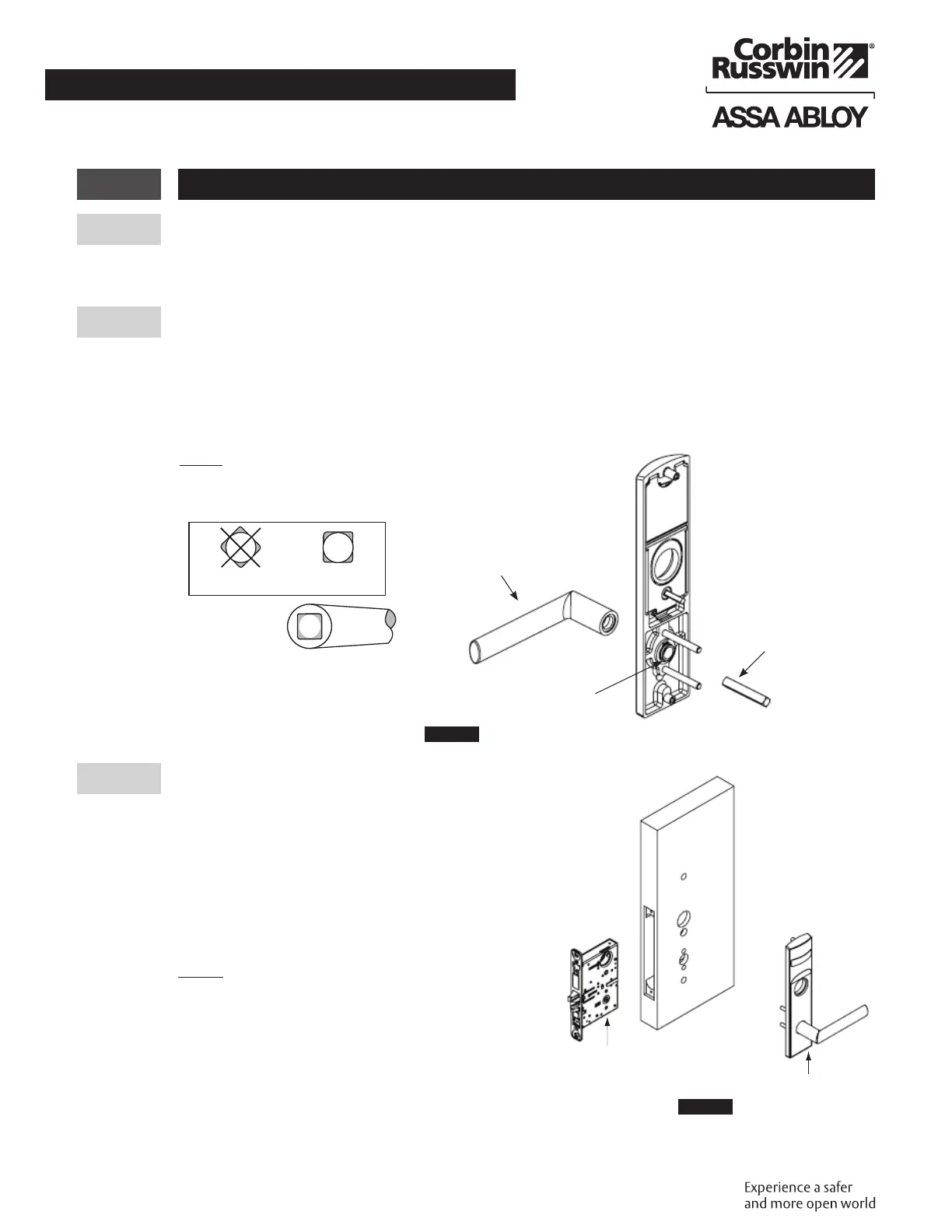
b MUSÉO® LEVERS ONLY: Attach Levers to Escutcheons
1. Thread lever onto adapter.
2. Insert spindle into adapter and fully tighten onto lever. Loosen smallest amount that allows spindle to
engage lever.
3. Verify correct spindle orientation with the lever held horizontally. (Figure10)
Lever
GOODBAD
NOTE:
Use correct spindle orientation.
(Figure10)
Lever
Adapter
Spindle
Figure10
c Install Lock and Outside Trim
1. Verify strike location according to template.
Clean out door pocket and door edge of debris.
2. Make sure handing of the lock matches handing of
door. Slide lock into the door and hold.
3. Slide outside lever and escutcheon assembly through
door; lock body and hold. (Figure11)
4. Verify indicator is in unlocked position.
NOTE:
• Keep door open while installing lock.
• Make sure lock is unlocked.
Outside of door
Inside of door
Lock
Outside
Escutcheon
Assembly
RH door
shown
Figure11
 Loading...