5
ML2000 Series Mortise Lock
Installation Instructions
Used with VN Escutcheon Trim and V Series Indicators
FM521 08/19
Copyright © 2019, ASSA ABLOY Access and Egress Hardware Group, Inc. All rights reserved. Reproduction in whole or
in part without the express written permission of ASSA ABLOY Access and Egress Hardware Group, Inc. is prohibited.
For installation assistance contact Corbin Russwin
1-800-543-3658 • techsupport.corbinrusswin@assaabloy.com
4 Rehanding Indicator (if necessary)
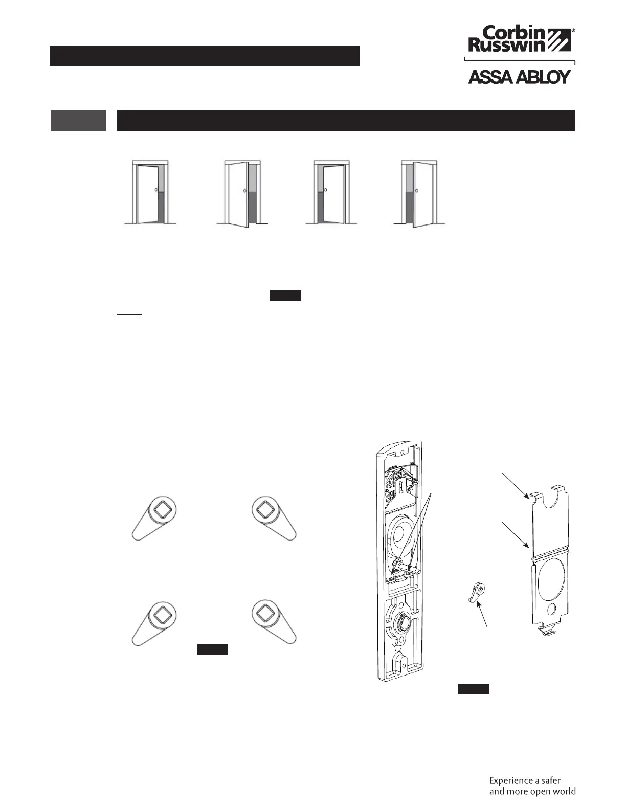
1. Verify hand and bevel of door. (Figure7)
LH
Left Hand
Hinges Left
Open Inward
RH
Right Hand
Hinges Right
Open Inward
LHRB
Left Hand
Reverse Bevel
Hinges Left
Open Outward
RHRB
Right Hand
Reverse Bevel
Hinges Right
Open Outward
Figure7
Note:
Stand on outside of locked door when determining door hand.
2. Remove indicator back plate by pulling out from top slot.
3. Remove spindle cam from assembly.
4. Position the spindle cam in the correct direction for door hand. (Figure8)
5. Slide spindle cam post into the correct slot of the display slide (Figure9).
6. Press back plate back into original position.
Note:
Verify handing on both outside and inside
indicators.
Door Hand:
RH/RHRB
Door Hand:
LH/LHRB
Spindle Cam Position
Inside Indicator
Outside Indicator
Outside Indicator
Inside Indicator
Figure8
Spindle Cam
Back
Plate
Plate slot
for removal
Display Slide
Slot
Figure9
 Loading...