26
6.1
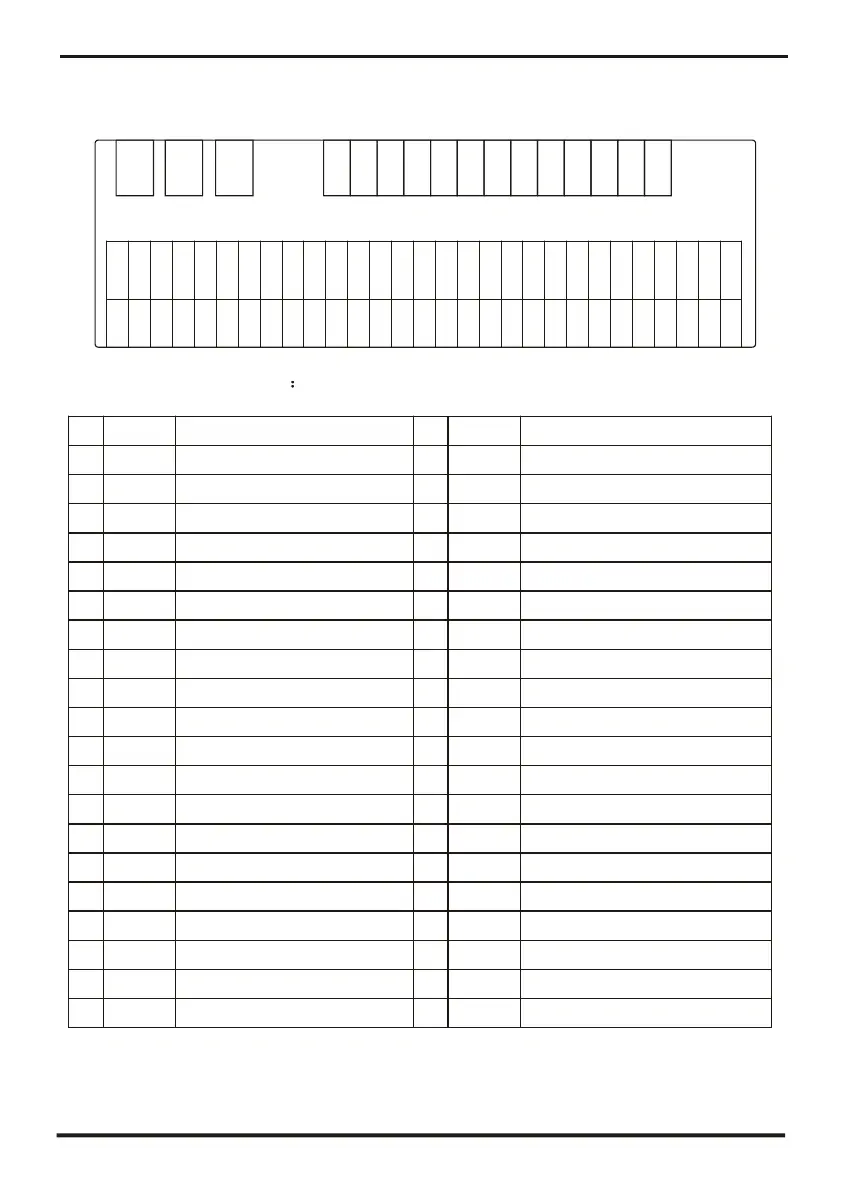
Connection of PCB illustration
12V
NET
DI 01
5V
AI 01
AI 02
AI 03
AI 04
AI 05
AI 06
AI 07
AI 08
AI 09
AI 10
A I11(50K)
A I12(50K)
DI 02
DI 03
DI 04
DI 05
DI 06
DI 07
DI 08
DI 09
DI 10
DI 11
DI 12
DI/D O 2
DI/D O
GND
GND
GND
GND
GND
GND
GND
GND
GND
GND
GND
GND
GND
GND
GND
GND
GND
GND
GND
GND
GND
GND
GND
GND
GND
GND
GND
GND
GND
Connections explanation
NO. Symbol
Meaning
NO. Symbol
Meaning
1
AC-L
Live line
21
DI 07
Water flow switch protection input
2
AC-N
Null line
22
DI 08
Electric heater overload protection input
3
RO 01
Compressor 1 output(220VAC)
23 DI 09
Compressor 1 overload protection input
4
RO 02
Compressor 2 output(220VAC)
24
DI 10
Compressor 2 overload protection input
5
RO 03
High speed of fan output(220VAC)
25
DI 11
System protection input
6
RO 04
Low speed of fan output(220VAC)
26
DI 12
Emergency switch input
7
RO 05
Water pump output(220VAC)
27
AI 01
Water input temperature input
8
RO 06
4-way valve output(220VAC)
28
AI 02
Water output temperature output
9
RO 07
Electric heater output(250VAC)
29 AI 03
System 1 fan coil temperature input
10
RO 08
Spray valve output(220VAC) 30
AI 04
System 2 fan coil temperature input
11
RO 09
Alarm system output(220VAC)
31 AI 05
Ambient temperature input
12
DI/DO 1
Mode indicator output
32
AI 06
System 1 antifreeze temperature input
13
DI/DO 2
Emergency switch output
33
AI 07
System 1 antifreeze temperature input
14
DI 01
Flow rate input
34
AI 08
System 1 suction temperature input
15
DI 02
System 1 high pressure protection input
35
AI 09
System 2 suction temperature input
16
DI 03
System 1 low pressure protection input
36
AI 10
No use
17
DI 04
System 2 high pressure protection input
37
AI 11(50K)
System 1 discharging temperature input
18
DI 05
System 2 low pressure protection input
38
AI 12(50K)
System 2 discharging temperature input
19
NET GND 12V
Connecting to the remote controller
39
CN1
System 2 electric expansion valve output
20
DI 06
Phase sequence protection
40
CN6 System 1 electric expansion valve output
N
L
RO 01
RO 03
RO 04
RO 05
RO 06
RO 07
RO 08
RO 09