S I G N A T U R E
15
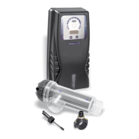
7.6.1. ELECTROLYSIS CELL INSTALLATION
The electrolysis cell is made of a transparent polymer in whose interior the electrodes are
placed. The electrolysis cell must be always installed indoors and after the pool lter, and
after any other equipment (heat pumps, control systems, etc.). The installation of the cell should
allow easy access to the installed electrodes by the user. It is highly recommended to install the
electrolysis cell VERTICALLY, in a place of the pipe that can be easily isolated from the rest of
the installation by two valves, so that the tasks of maintenance can be carried out with no need
of partial or total draining of the swimming pool.
Where the cell is installed on a by-pass (recommended option), a valve to regulate the ow must
be introduced. Previously to installation, please consider the following commentaries:
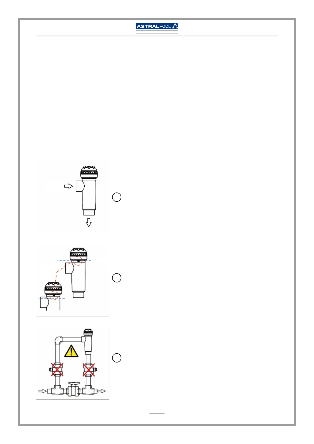
Flow direction marked in the cell must be respected.
Recirculation system must guarantee the minimum ow
stated in the Table of Technical Specications (see section 8
from the Operation Manual).
The system ow detector activates if there is not recirculation
(ow) of water through the cell or if ow is very low. If
electrolysis gases are not properly removed through the
electrolysis cell, the generated gas bubble electrically
isolates the auxiliary electrode (electronic detection).
Therefore, when locating the electrodes in the cell, the level
sensor (auxiliary electrode) will have to be located in the
higher area of the cell. The safest orientation is shown in the
recommended installation diagram.
WARNING: if the in-out valves of the electrolysis cell are
closed simultaneously, the ow detector (gas detector)
will not work correctly, with the consequent risk of cell
breakdown. Although this situation is extremely unusual,
since the Astralpool Chlore Elite System has an additional
external ow detector (ow switch), it can be easily avoided
once the equipment has been installed, by locking at opened
position the return valve to the swimming pool, so it cannot
accidentally be manipulated.
FlowFlow
FLOW
DETECTOR
(GAS)
CRITICAL
WATER LEVEL
GAS
WATER
FLOW
DETECTOR
(GAS)
CRITICAL
WATER LEVEL
GAS
WATER
1
2
3