S I G N A T U R E
17
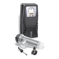
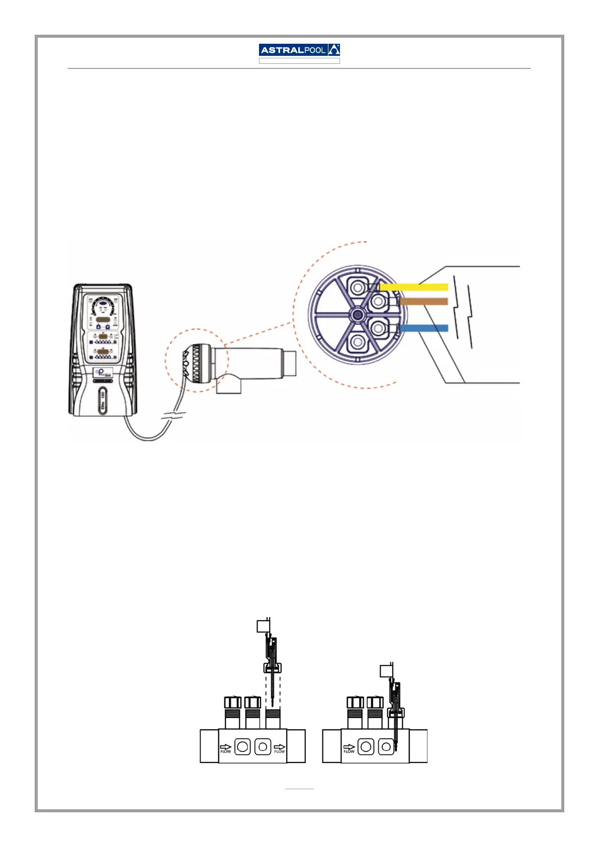
7.6.2. ELECTRICAL CONNECTION OF THE ELECTROLYSIS CELL
Make the interconnection between the electrolysis cell and the power supply according to
the following scheme. Due to relatively high current intensity circulating do not modify or cut
either the length or section of the supplied cables without making a previous consultation to an
authorized Astralpool distributor. The cable connecting the electrolysis cell and the power supply
must necessarily be of the maximum length recommended in the Manual: Elite 60 / 42353, 7.5
m.; Elite 100 / 42354, 4.0 m.; Elite 160 / 42355, 3.0 m.
Flow detector (gas)
Production
electrodes
YELLOW
BROWN
BLUE
7.6.3. INSTALLATION OF THE EXTERNAL FLOW DETECTOR
Besides the internal ow detector (gas detector) installed in all Astralpool Chlore equipment, the
Elite range systems have an additional mechanical ow detector (ow switch).
• Glue the sensor holder to a section of the pipe at the entrance to the electrolysis cell. It
should always be installed in a horizontal position relative to the ground.
• Install the ow detector (ow switch) supplied vertically in the sensor holder supplied with
the equipment.