S I G N A T U R E
22
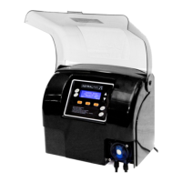
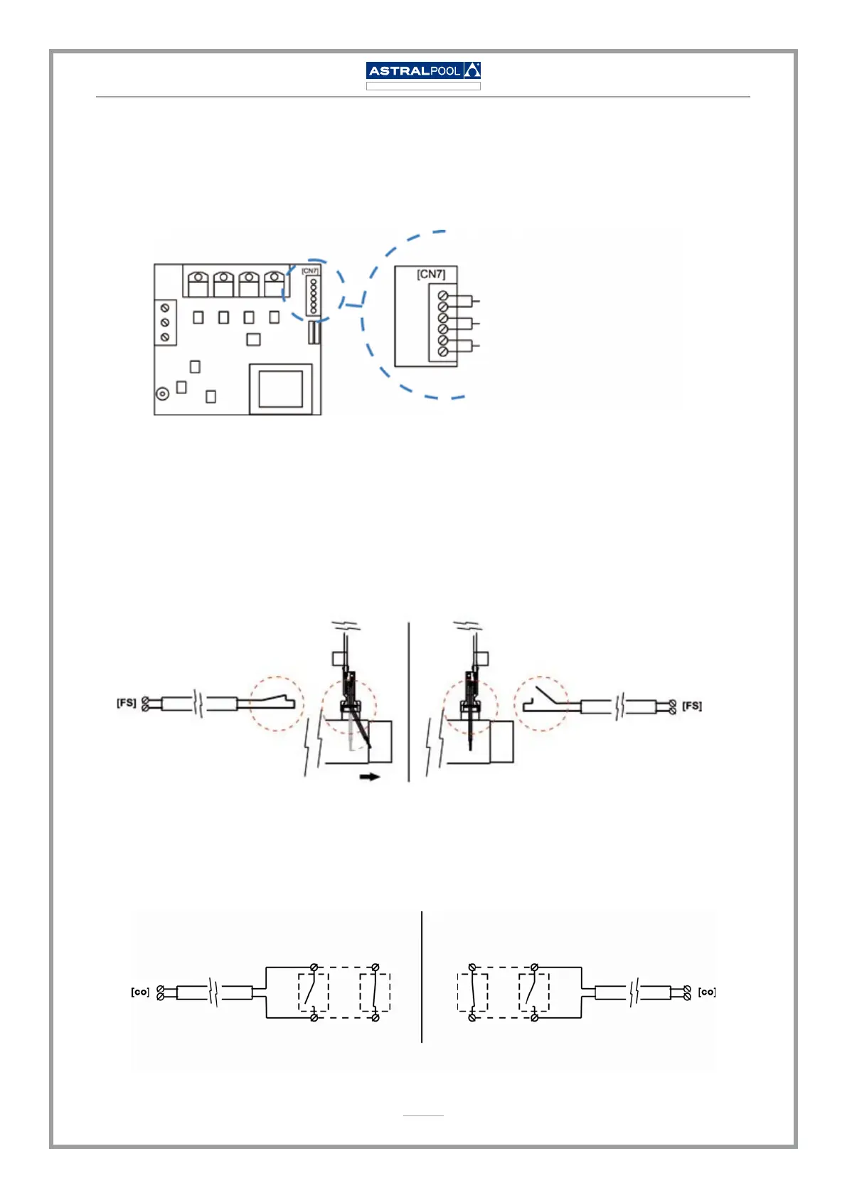
Besides basic operations, the AstralPool Chlore Elite electrolysis system has two inputs for
voltage-free contacts, enabling the connection of additional external controls. They are located
on connector [CN7] of the unit’s main circuit, on the base.
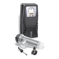
EXTERNAL FLOW DETECTOR [FS]
N/A
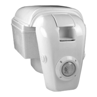
AUTOMATIC COVER [CO]
The logic associated to these two inputs can be programmed during the system conguration
process. (see next section).
[FS] EXTERNAL FLOW DETECTOR CONTROL: input for potential-free contact. When the
contact connected to this input is open (external ow detector at rest), the electrolysis system
switches off due to the ow alarm. Connect the external ow detector wiring to the respective
input [FS] on the unit’s main control card.
Input [FS] congured as [FS1c]
FLOW
System running System stopped
Flow alarm
[co] AUTOMATIC COVER CONTROL: input for potential-free contact. Depending on the
status of the contact connected to it on the automatic cover’s electric panel, this input ena-
bles you to programme a reduction of the equipment’s output current to a percentage of its
nominal value.
Auxiliary contact NO
Automatic cover
Open Closed
Auxiliary contact NC
Automatic cover
Open Closed
Congure [co] as [co1c]
Production is reduced
when closed auxiliary contact
Congure [co] as [co1o]
Production is reduced
when open auxiliary contact
•
•
•