18/46
phase from 0° to 180° inverts the direction of displacement (Figure 5-1). The
amplitude of the Act. 3. may be different from one direction of movement to the other.
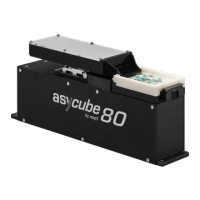
Figure 5-1: Asycube 50 and 80 – Actuator disposition and example
(green arrow) (solid line: 0° phase, dashed line: 180° phase)
• If the parts do not move exactly towards the desired target, one can adjust the
amplitude of the two in-plane actuators (Act.1 and Act.2) in order to correct the
displacement direction of the parts.
NOTE:
The hints provided are general and may not be perfectly suited to your Asycube. We
recommend the use of vibration set 26 as a starting point, as it is configured and tested on
your product using a standard part.
Table 5-2 below illustrates the directions of standard platform vibrations.
Forward
(A)
Forward left
(B)
Forward right
(C)
Left (D)
Right
(E)
Backward
(F)
Backward left
(G)
Backward right
(H)
 Loading...