QSG_F600.415.00_EN_01 / 2019-04-16
17 / 38
Pin number Inputs / outputs Description
1 Input 1 RESET
2 + 24 V DC Common
3 Input 2 START
4 + 24 V DC Common
5 Input 3 Program selection
6 Input 4 Program selection
7 Input 5 Program selection
8 Input 6 Program selection
9 Input 7 Program selection (programmable input)
10 Output Common floating output
11 Output Pass part
12 Output Test fail part
13 Output Not used
14 Output Warning
15 Output End of cycle
16 0 V Ground
The device can be energized through theJ11 connector of the relay board (except if internal
supply option):
0V to the pin16
24VDC to the pin2 or4.
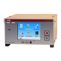
Program selection extension connector (J10) (option)
The J10 connector is an extension of the J11 connector that enables the selection of128
programs.
Characteristics
— Inputs
• Activation: + 24 V DC.
Pin number Inputs/outputs Description
I8 Input 8 Program selection from 33 to 64 (programmable input)
I9 Input 9 Program selection from 65 to 128 (programmable input)