27
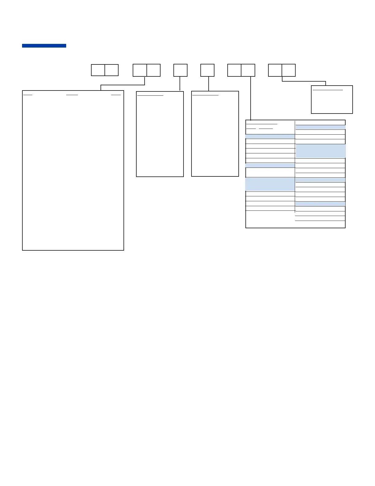
Product Code
Information
Code Options
Digital Input w/Alarm
40 = Switch Closed
41 = Switch Open
42 = 5 V Input
Communication RS-485
Modbus
®
Protocol w/
Contact/Digital Input
45 = RS-485, No Switch
46 = Switch Closed
47 = Switch Open
48 = 5 V Input
Transducer Excitation
50 = 10 Vdc
51 = 12 Vdc
52 = 15 Vdc
53 = 5 Vdc
Aux Output/PV Retransmit
60 = 4 to 20 mA
61 = 1 to 5 V
62 = 0 to 20 mA
63 = 0 to 5 V
Input Range Code
“E” TC 0 to 1292° F EF
“E” TC -18 to 700° C EC
“J” TC 0 to 1400° F JF
“J” TC 0 to 750° C JC
“K” TC 0 to 2460° F KF
“K” TC 0 to 1349° C KC
“N” TC 0 to 2370° F NF
“N” TC 0 to 1300° C NC
“R” TC 0 to 3200° F RF
“R” TC 0 to 1750° C RC
“S” TC 0 to 3200° F SF
“S” TC 0 to 1750° C SC
“T” TC -200 to 600° F TF
“T” TC -100 to 300° C TC
100 ohm RTD -328 to 1562° F PF
100 ohm RTD -200 to 850° C PC
100 ohm RTD -199.0 to 450.0° F DF
100 ohm RTD -100.0 to 225.0° C DC
1000 ohm RTD -328 to 1562° F XF
1000 ohm RTD -200 to 850° C XC
1000 ohm RTD -199.0 to 450.0° F ZF
1000 ohm RTD -100.0 to 225.0° C ZC
1 to 5 V Scaleable L1
0 to 5 V Scaleable L4
10 to 50 mV Scaleable L2
0 to 50 mV Scaleable L5
4 to 20 mA* Scaleable L3
0 to 20 mA* Scaleable L6
0 to 10 Vdc Scaleable L7
2 to 10 Vdc Scaleable L8
0 to 1 Vdc Scaleable L9
Output 2 Code
0 = None
B = Relay, N.O.
E = 0 to 20 mA
F = 4 to 20 mA
(500 ohm max)
G = 4 to 20 mA
(800 ohm max)
P = Pulsed 20 Vdc or
35 mA
S = Pulsed 20 Vdc or
17 mA
T = Solid-State Relay
V = 0 to 5 Vdc
X = 0 to 10 Vdc
Y = Relay, N.C.
Special Options
00 = None
Consult factory for
available special options
you may need for your
application.
- - - - 0 0
1 6
-
Output 1 Code
0 = None
B = Relay, N.O.
E = 0 to 20 mA
F = 4 to 20 mA
(500 ohm max)
G = 4 to 20 mA
(800 ohm max)
P = Pulsed 20 Vdc or
35 mA
S = Pulsed 20 Vdc or
17 mA
T = Solid-State Relay
V = 0 to 5 Vdc
X = 0 to 10 Vdc
Y = Relay, N.C.
Standard Options
Code Options
00 = None
Alarms
10 = Dual SSR, N.O.
20 = Dual Open Collector
21 = Dual 24 Vdc
22 = Dual SSR, N.C.
23 = Relay, N.O.
Communications
30 = RS-232
(Athena+ Protocol)
Communication, RS-485
Athena+ Protocol w/Contact/
Digital Input
31 = RS-485, No Switch
36 = Switch Closed
37 = Switch Open
38 = 5 V Input
 Loading...