1
Installation
Bezel
Case Clip
Grips
Rubber Gasket
Customer Panel
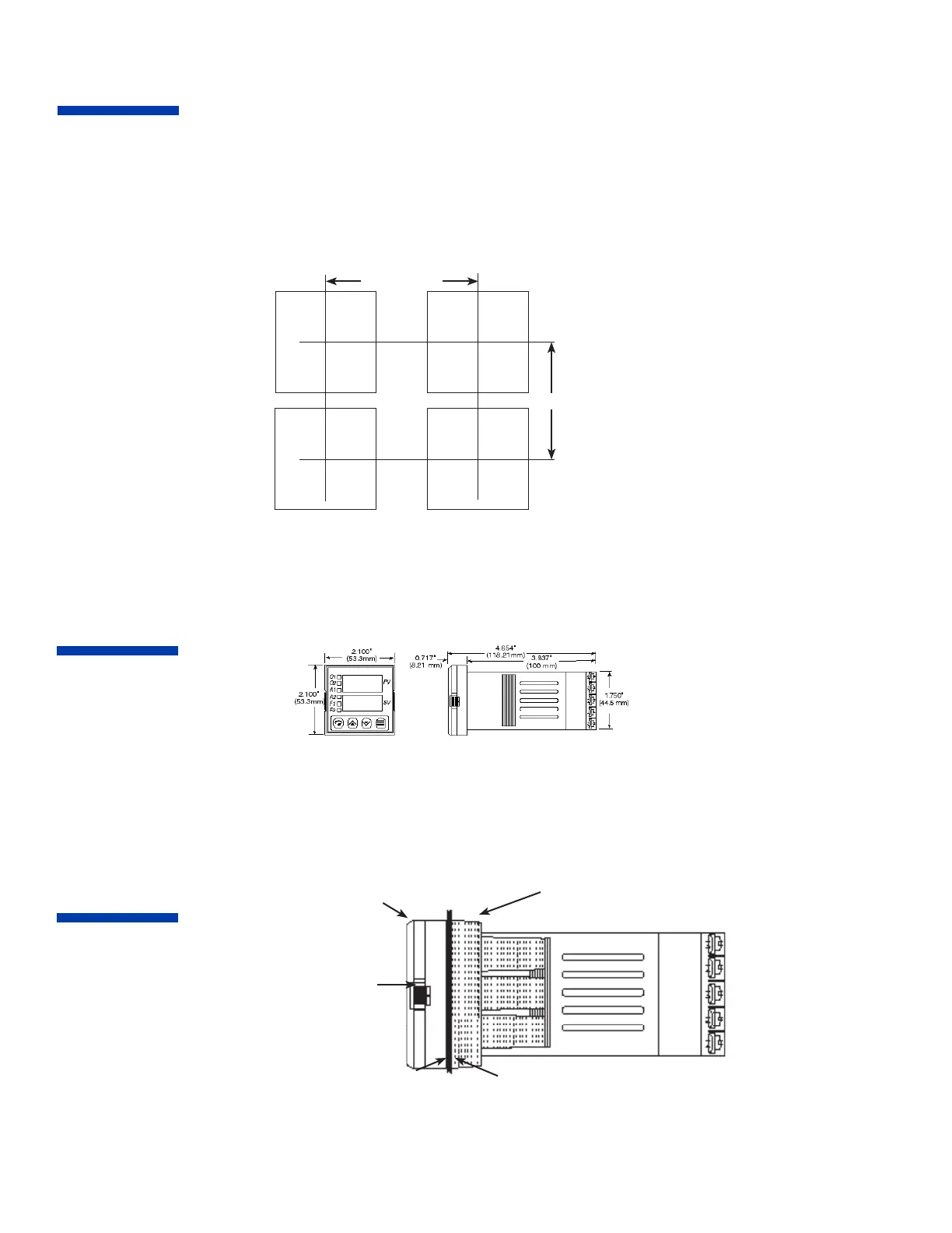
Measurements between centerlines of panel cutouts are the minimum recommended.
Unpacking and Inspection
1. Inspect shipping carton for obvious signs of mishandling.
2. After removing the controller from the shipping carton, inspect it carefully for damage. Never attempt to install and use a damaged
unit.
3. Verify that the ordering code number indicated on the side of the controller matches what was ordered.
C
L
C
L
C
L
C
L
2.850” (72.4 mm)
2.150” (54.6 mm)
Figure 2. Case Dimensions
Prior to mounting the Series 16 in your panel, make sure that the cutout opening is of the right size, 1.771” x 1.771” (45 mm x 45 mm),
and deburred to enable a smooth fit. A minimum of 4” (100 mm) of depth behind the panel is required.
Dimensions
Mounting
Figure 3. Series 16 Mechanical Components
Insert the Series 16 through the front panel cutout and slide the mounting collar back onto the unit from behind the panel. Push the
mounting collar up tight to the back of the mounting panel.
Figure 1. Recommended Panel Layout for Multiple Controllers
 Loading...