3.4.6 Pump down operation (Refrigerant collecting
operation) outdoor unit
" Ensure that the general electrical power
supply has been cut off before starting any
repair work.
"
Stored energy: after disconnecting power
supplies wait 1 minute before accessing the
internal parts of the equipment.
Perform the following procedures to collect the
refrigerant.
- 1- Turn OFF the start/stop switch
(ref. 3, gure 10, page 11). Disconnect the outdoor
units power supply.
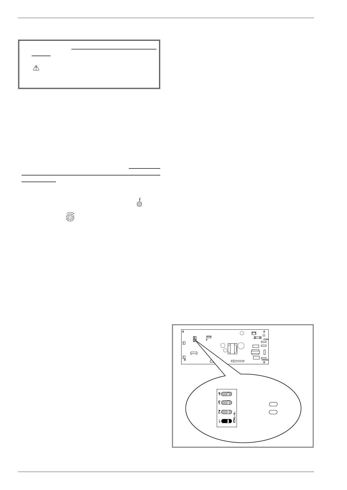
- 2- Remove the front panel. Open the power control
box. Then turn ON the DIP SW1 on the interface
board,
- 3- Reconnect the power supply. Turn ON the start/
stop switch.(Green and Red LED on the board start
ashing ; 1 sec. on / 1 sec. off repeated). The outdoor
unit begins cooling operation about 3 minutes after
switching ON.
- 4- Rapidly: Set the parameter 7700 (Relay output
QX1) to ON. => The pump works normally.
Reminder: Press OK. Hold on the key
for 3s
and select the level of access* used with the aid
of the knob . Conrm with the key OK.
* Choose “Specialist” level / Inputs / outputs test.
- 5- Close the liquid valve on the outdoor unit 30 s
maximum after operation starts.
- 6- Close the gas valve on the outdoor unit as soon as
the pressure is lower 0.02 bar relative reading on the
Manifold or 1-2 minutes after closing the liquid valve,
while the outdoor unit keeps running.
- 7- Disconnect the power supply.
- 8- The refrigerant collecting operation is over.
Remarks:
- The pump down operation cannot be activated even if
DIP SW1 is changed while heat pump's power is ON.
- Do not forget to turn back DIP SW1 on the interface
board to OFF, after the pump down operation has
been completed.
- Select the "AUTO" heating mode.
- When the pump down operation is repeated,
temporarily turn OFF the start/stop switch after opening
the closed valves (both liquid and gas).
Interface card
LED2
(green)
LED1
(red)
OFF
ON
gure 27 - Location of DIP switches and LED
on the hydraulic unit interface card
Installation and operation manual "1734 - EN"
Heat pump air/water split 1 service alféa extensa +
- 28 -