EP5PTI19 HR10-MT EN Service
© Atlas Copco Industrial Technique AB - 9839 0661 01
21
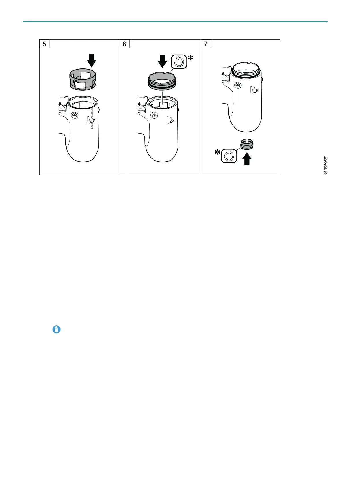
* For correct tightening torque see Spare parts list.
Position of the stop pin in Pulse unit
The position of the stop pin is correctly set at the factory. If the position has to be reset or adjusted due to
service or replacement of spare parts, follow the instructions below.
Measurements
■
D is the opening diameter for the gauge.
Adjusting the position of the stop pin
1. Fit an 2.5 mm Allen key in the adjustment screw.
2. Hold the Pulse unit with both stop surface of inertia body and anvil in horizontal position and the Allen
key pointing downwards.
3. Press the inertia body to open the hole for the gauge.
4. Place a gauge, for instance a drill bit, with the correct diameter of D (see table Gauge diamater) in
the hole.
5. Adjust the opening by turning the adjustment screw 45 degrees at the time until the gauge is in line
with the pulse unit.
Avoid unnecessary turning of the adjustment screw.
■
Turn the screw anti-clockwise to raise the gauge.
■
Turn the screw clockwise to lower the gauge.
6. Check that the gauge is correctly inserted by repeatedly pressing and releasing the inertia body. The
gauge should return to the correct position in line with the Pulse unit.
7. Apply Loctite 290 to the adjustment screw.
 Loading...