Do you have a question about the Atlas Copco Xc1004 and is the answer not in the manual?
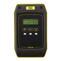
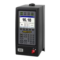
Highlights key display elements including pressure gauge, status icons, fuel level, additional measurements, and running hours.
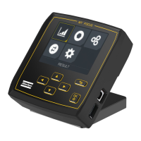
Details the purpose and operation of the Start, Stop, Measurement, and Alarm buttons for user interaction.
The Atlas Copco Xc1004 is a controller designed for managing and monitoring compressor operations, featuring a user-friendly interface with dynamic button functions and comprehensive diagnostic capabilities.
The Xc1004 controller provides real-time monitoring of various compressor parameters and allows for easy interaction with the machine. Its self-explanatory interface utilizes buttons whose functions change depending on the active menu, with icons in the four corners of the display indicating the current function of each button. This design aims to simplify navigation and operation.
Key display elements and their functions:
Button Functions:
The Xc1004 is designed for intuitive operation, allowing users to start, stop, and monitor their compressor with ease.
Starting the Compressor:
Stopping the Compressor:
Advanced Settings:
Alarm Management:
The Xc1004 controller assists in maintenance by providing diagnostic information and alerting operators to potential issues.
Alarm Codes and Meanings: The controller displays a list of common alarm codes to help operators understand and address issues. Some examples include:
These alarms help operators identify the root cause of problems, enabling timely corrective actions or informing service technicians. For codes not listed or in case of doubt, Atlas Copco service technicians are available for support.
Documentation: This Quick Start Guide provides basic information, but it is crucial to consult the comprehensive Instruction Manual delivered with the machine. The manual contains detailed information on correct usage, safety precautions, and guidelines for preventive maintenance. It is recommended to keep the manual with the compressor for easy access by any operator.
| Brand | Atlas Copco |
|---|---|
| Model | Xc1004 |
| Category | Controller |
| Language | English |