The EBL Drives and Controllers series from Atlas Copco offers a range of devices designed for precise and controlled tightening applications, primarily with EBL screwdrivers. This manual covers several components including EBL Drive, EBL Drive Plus, EBL ST Controller, EBL LS Controller, EBL RE-Drive, and EBL RE Module, providing a comprehensive guide for their installation, operation, and maintenance.
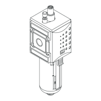
EBL Drive and EBL Drive Plus
Function Description:
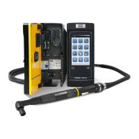
The EBL Drive and EBL Drive Plus are power packs designed to operate EBL screwdrivers. They provide the necessary power and control for the screwdriver's operation, including speed selection. The EBL Drive Plus offers enhanced capabilities compared to the standard EBL Drive.
Usage Features:
- Installation: The power packs come with two attachment plates for secure mounting to a surface, either horizontally or vertically, in the work area. They connect to the EBL drive with four screws.
- Operating Instructions:
- Connection: The tool cable connects to the tool and the drive (port A).
- Power On/Off: A POWER switch controls the unit's power.
- Speed Selection: A SPEED switch allows selection between two rundown speeds:
- HI: 100% speed
- LOW: 70% speed
- Torque Adjustment: Torque is adjusted using a torque adjustment key, which is included with the EBL tool.
Important Technical Specifications:
- The maximum speed depends on the setting of either EBL Drive or EBL Drive Plus. If the setting is LOW, the maximum is 70%.
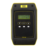
EBL ST Controller
Function Description:
The EBL ST Controller is designed to work with EBL screwdrivers featuring a soft-start function ("ST"). It regulates the speed during start-up and controls the maximum speed of the screwdriver.
Usage Features:
- Driving System: Connects an EBL screwdriver with soft-start function to the controller. The controller sends appropriate signals to the screwdriver to regulate speed during start-up and maximum speed.
- Speed Setting System:
- EBL12-ST: 320 RPM ±20% (LOW), 910 RPM ±20% (HIGH)
- EBL25-ST: 250 RPM ±20% (LOW), 930 RPM ±20% (HIGH)
- EBL35-ST: 180 RPM ±20% (LOW), 700 RPM ±20% (HIGH)
- Soft Timer Setting System: Adjusts the low start speed using the soft-start timer function.
- (-) position: 0 seconds
- (+) position: more than 3 seconds
- Torque Setting System: Adjusts the torque using the Torque adjustment key included with the tool.
- EBL 12 ST: 0.2 Nm (MIN) - 1.2 Nm (MAX)
- EBL 25 ST: 1.0 Nm (MIN) - 2.5 Nm (MAX)
- EBL 35 ST: 1.0 Nm (MIN) - 3.5 Nm (MAX)
- Connectors and Adjustments:
- Connector for RE cable from EBL RE-ST tools.
- Connector for EBL ST tool through a 6-pin driver cable.
- Adjustment for soft start timer: Sets the timer for low speed start. Adjusting towards '+' increases time, towards '-' decreases time.
- Adjustment for soft start speed: Controls rotation speed in the soft start phase. Adjusting towards '+' increases speed, towards '-' decreases speed.
- Cable that connects with EBL Drive.
- Setting of EBL Model: The EBL ST Controller can be opened to select the correct plug for the specific EBL model (e.g., EBL25-ST, EBL35-ST, EBL12-ST).
- Important Note: A LOW rotation setting with maximum or just below maximum torque can lead to poor results. Use the HI-setting when utilizing a high torque setting. The maximum speed depends on the EBL Drive or EBL Drive Plus setting; if LOW, the maximum is 70%. The ST function is only valid for Forward Rotation; Reverse Rotation speed is fixed to the maximum speed of the EBL screwdriver.
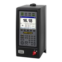
EBL LS Controller
Function Description:
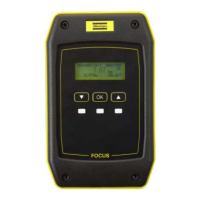
The EBL LS Controller is designed to connect an EBL brushless screwdriver with a soft-start function ("LS"). It receives and sends feedback through the sensor signal to the screwdriver, which gives variable movement in the rotation speed.
Usage Features:
- Driving System: Connects an EBL brushless screwdriver with soft-start function to the controller. The controller receives and sends feedback through the sensor signal to the screwdriver, providing variable movement in rotation speed.
- Control System: Controlled by the combination of whole sensor signal in the brushless motor and the PWM signal from the controller.
- Speed Setting System:
- EBL03-LS/EBL03-LS-RE: 320 RPM ±10% (LOW), 870 RPM ±10% (HIGH)
- EBL03-Q-LS/EBL03-Q-LS-RE: 320 RPM ±10% (LOW), 870 RPM ±10% (HIGH)
- EBL12-LS/EBL12-LS-RE: 320 RPM ±10% (LOW), 910 RPM ±10% (HIGH)
- Torque Setting System: Adjusts the torque using the torque adjustment key included with the tool.
- EBL03-LS/EBL03-LS-RE: 0.05 Nm (MIN) - 0.3 Nm (MAX)
- EBL03-Q-LS/EBL03-Q-LS-RE: 0.05 Nm (MIN) - 0.3 Nm (MAX)
- EBL12-LS/EBL12-LS-RE: 0.2 Nm (MIN) - 1.2 Nm (MAX)
- Connectors/Display:
- Connector for RE cable from EBL RE-LS tools.
- Connector for EBL LS tool through a 6-pin driver cable.
- Not used.
- Screwdriver speed adjustment during the soft timer: Turning the arrow to the direction of the arrow (+) increases rotation speed, turning to the opposite direction (-) decreases speed.
- Cable that connects with EBL drive.
- Important Note: A LOW rotation setting with maximum or just below maximum torque can lead to poor results. Use the HI-setting when utilizing a high torque setting. The LS function is only valid for Forward Rotation. The speed of Reverse Rotation is the same as the setting of EBL Drive, EBL Drive Plus or EBL RE-Drive.
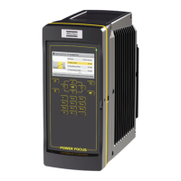
EBL RE-Drive and EBL RE Module
Function Description:
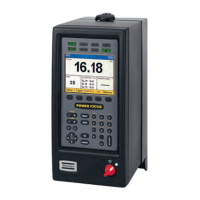
The EBL RE-DRIVE and EBL RE Module are screw counters used to run and monitor work with EBL screwdrivers, ensuring excellent repeatability and a steady quality level. The RE-DRIVE can directly drive a screwdriver, while the RE Module connects to a separate Drive.
Usage Features:
- Main Functions:
- Tracks the number of screws tightened and verifies work completion.
- Distinguishes between OK tightening and re-hit tightening.
- Verifies minimum time span for each tightening and per work piece.
- Controls external devices like total counters or jigs for fixing work pieces.
- Front Panel (EBL RE-DRIVE / EBL RE-MODULE):
- Operating Display LED:
- Green: Power on
- Orange: Screwdriver function enabled
- Digital Display: Shows the set number of screws and counts down.
- Reset Switch: Resets counter functions, interrupts valve signal output, and releases external devices. Returns display to set number.
- 6-Pin Tool Connector: Connects the screwdriver cord.
- Function Switch 1 (F1): Enters Change Function Mode (press >1s after reset). Pressing >1s in Change Function Mode causes a buzzer sound and exits the mode.
- Function Switch 2 (F2) (x10): Increases numbers in increments of 10.
- Function Switch 3 (F3) (x1): Increases numbers in increments of 1.
- HI/LO Speed Switch (Only RE-DRIVE): Changes the free speed of the tool.
- Power Supply Main Switch (Only RE-DRIVE): Turns the power supply on/off. LED inside the switch lights up when on. Protection circuit automatically turns off power if screwdriver locks or overloads.
- Rear Panel:
- COMP (Output Signal): For Batch OK. Outputs for 0.1 seconds after Tool Disable Timer 2 elapses from Tightening OK of the last screw.
- RESET (Input Signal): Resets counter functions, interrupts VALVE signal, releases external devices. Same function as front panel Reset Switch.
- SET (Input Signal): For Work Set signal. After Tool Disable Timer 1 elapses from SET input, Operating Display LED lights, screwdriver becomes operational, and VALVE signal is generated.
- GND: Ground Terminal.
- +DC24V: Output power for external equipment (Max 0.2A).
- VALVE: Enables solenoid valve control of external devices (e.g., jigs).
- BZ (Output Signal): Similar to COMP signal, synchronized with Tool Disable Timer 2.
- ER BZ (Output Signal): Error signal. Generated if SET signal is interrupted. Output continues until reset or last screw in batch is tightened.
- AC Inlet Power inlet (Only RE-DRIVE): Power inlet.
- Fuses (Only RE-DRIVE): Fuses and compartment for spare fuses (T5A).
- Drive connector (Only RE Module): Connects to EBL Drive / EBL Drive Plus.
- Input Signals (SET, RESET): Photo coupler input. Max input current 10 mA, min 2 mA for detection. For open collector, connect collector to input terminal and emitter to +DC24V terminal.
- Output Signals (COMP, VALVE, BZ, ER BZ): Open collector output.
- Max rated load per output terminal: 30V DC/80 mA.
- Max total current for all output terminals: 200 mA. Exceeding this limit can damage transistors.
- If an output terminal is short-circuited to 0V DC, max current is exceeded.
- Do not apply voltage to output terminals. For external equipment with relays or solenoid valve coils, add a diode to absorb reverse voltage.
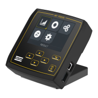
- Settings: Function settings are performed using F1, F2, and F3 buttons, each with a corresponding seven-segment LED display.
- Enter Settings: Press F1, then Reset until F1 LED shows 'P'. Release F1. Select setting with F1, adjust with F2/F3. Exit by holding F1 until buzzer sounds twice and F1 LED shows '8'.
- Main Setting Table:
- Batch number: Set number of screws in batch (1-99).
- Re-hit timer: Set time before new tightening (0.00-0.99 s).
- Tool Disable Timer 1: Pause timer after SET signal (0.0-3.9 s). Generates valve output signal.
- Tool Disable Timer 2: Pause timer after end of batch (0.0-3.9 s).
- Reverse Timer: Set time for reverse count on display (0.1-1.0 s).
- System setting mode: Handles display (counter ON/OFF), Buzzer (ON/OFF), reverse count ON/OFF.
- System Setting Tables (LED F2): Controls Batch display, Batch buzzer, Reverse count.
- System Setting Tables (LED F3): Controls Screwdriver operation (SET-signal determines operation or always allowed) and Tightening buzzer (sounds on OK tightening).
Maintenance Features:
- Troubleshooting:
- Unit does not supply power:
- Confirm power supply cord is correctly connected to voltage outlet.
- If unplugged, reconnect and turn on main power switch; check if LED lights.
- Confirm fuse has not failed. If failed, replace with spare and turn on main power switch; check if LED lights.
- Screwdriver will not function:
- Contact supplier if unit does not power up after fuse replacement.
- Ensure unit is not set in factory default mode (system setting mode 00).
Important Note: Many events in the operating environment can affect tightening process validation. It is required to check installed torque and rotational direction after any event that influences tightening results, such as initial installation, changes in part/bolt/screw batch, tool/software/configuration/environment changes, air/electrical connections, line ergonomics, process/quality procedures, operator changes, or any other influencing factor. This check should ensure joint conditions haven't changed, be done after installation/maintenance/repair, and occur at least once per shift or at suitable frequency.