Do you have a question about the Atlas Copco Power Focus 600 and is the answer not in the manual?
Essential safety guidelines and operational procedures for user protection.
Notes on the use of interface screenshots as examples in the manual.
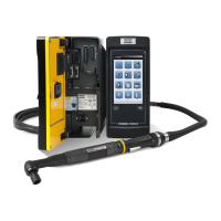
Overview of the system's structure and components.
Details the Intelligent Application Module, its contents, and location.
Discusses QIF accessories and the benefits of serial bus connectivity.
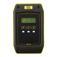
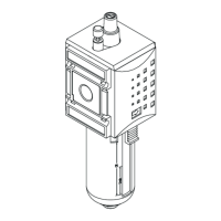
Describes the sealed I/O Expander for demanding environments.
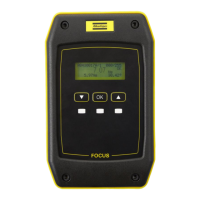
A socket tray with LEDs to guide users through sequences.
An external device for general purpose lamps and switches.
A flexible light and switch device for interface with controllers.
Devices used to automate assembly and selection of tightening programs.
Information for service personnel regarding installed controller software.
The unique version number of the software currently activated.
Details about auxiliary, base, connector, IT, and TPLC boards.
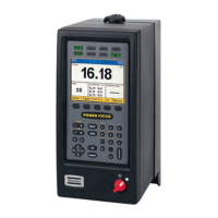
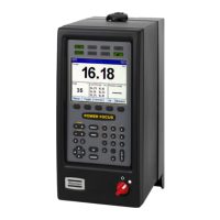
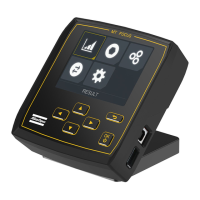
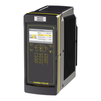
Overview of the controller interface and its functionalities.
Details the display, special keys, navigation keys, and keypad on the front panel.
Explains the header, content, and footer areas of the controller display.
Details the function of each button on the controller's keypad.
How to configure and program the controller via a web browser.
Lists the eight main menus for configuration, administration, and maintenance.
Details how to set up and configure tightening programs (Psets).
Describes how to set up and configure batch sequences.
Access information, calibrate, and maintain the connected tool.
Administer software, view hardware, and manage configurations.
Configure internal I/Os and external accessories like scanners.
Access tightening results, events, and NOK ratios.
Configure network, PIN, language, date, time, and units.
Provides useful help sections and information on controller functions.
Instructions for mounting and connecting the Power Focus 600 controller.
Steps to connect and configure the controller on a Local Area Network.
How to connect directly to the controller from a PC via Ethernet.
Selection of supported languages for the controller interface.
How to set and recalculate torque values in different units.
Setting the system date and time for accurate event logging.
How to activate trace functionality to monitor tightening behavior.
Procedures for enabling, disabling, and setting a PIN for controller security.
How to gain access to the controller when the PIN lock is active.
Details the pin configuration for the external Emergency Stop interface.
Instructions on how to reset an activated emergency stop function.
Describes the four fundamental stages of the tightening process.
Explains the use of batch sequences for performing multiple tightenings.
Covers parameters like Free order for batch sequence configuration.
Defines essential parameters like Pset, Batch size, and Socket for batch setup.
Configuration steps for using a scanner with batch sequences.
Method for selecting barcode characters to match pre-defined strings.
User prompts and requirements for exporting/importing data and configurations.
Details the structure and format of exported zip archives and CSV files.
Step-by-step guide to perform motor tuning for tool optimization.
How to set up the tool and controller for accurate calibration.
The formula used to calculate the new tool calibration value.
How to configure an alarm for the next scheduled calibration.
Installing software updates using a USB flash drive.
Installing software updates via the controller's web interface.
Stored information on tightening status, date, time, and torque.
Stored information on event occurrence, ID, description, and severity.
Lists Psets with the highest ratio of non-conforming tightenings.
Terminates tightening immediately upon detecting a rehit.
Completes all stages before marking a rehit to ensure full tightening.
Fast, ergonomic tightening using the tool's maximum speed.
Reduces preload scatter via an initial step with specific torque and speed.
Adds a pause between steps to counteract short-term relaxation effects.
Tightens, loosens, then retightens to address relaxation and scatter.
Primarily for testing; rotates the socket in free air at specified angle and speed.
Tutorial on activating a Pset and setting the target torque for a tightening.
How to select and activate a configured tightening program (Pset).
Renaming a tightening program (Pset) for better identification.
Configuring various behaviors to fine-tune tightening performance.
Guide to setting up batch sequences using scanners and socket selectors.
How to connect and configure a torque reference transducer for calibration.
Choosing an appropriate Pset for performing tool calibration.
Calculating and storing the new calibration value to correct tool readings.
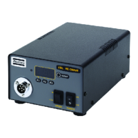
Identifies connections and switches on the front of the controller.
Identifies connections on the underside of the controller.
Lists event codes, their types, names, descriptions, and recommended procedures.
Provides guidance for diagnosing and resolving common system issues.
| Brand | Atlas Copco |
|---|---|
| Model | Power Focus 600 |
| Category | Controller |
| Language | English |