- 11 -
Operating manual SUNTEST XLS / XLS+
3
Description of equipment
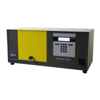
Figure 3
!
Air outlet for Xenon lamp cooling
"
Port for connecting the optional cooling equipment
/flooding equipment
#
Power plug with connecting cable
$
Air inlet opening - test chamber
%
Air inlet opening Xenon lamp cooling
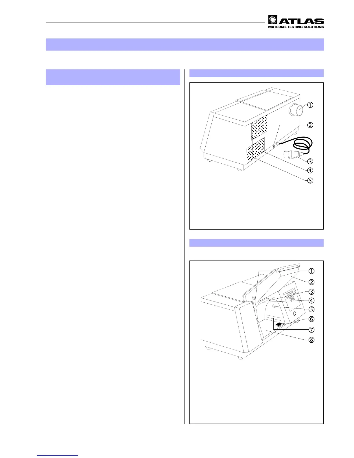
Figure 4
!
Gas pressure spring
"
Test chamber door
#
Reflector
$
Xenon lamp
%
Photodiode for measurement of the irradiance
&
Black standard sensor (BST)
'
Air inlet for temperature control in the
test chamber
(
Sample table
Test chamber: Fig. 4
• Gas pressure spring
!
for easy opening / closing the
test chamber door
"
.
• The reflector
#
is located in the test chamber, and
the Xenon lamp
$
at the top of the test chamber,
• The photo-diode
%
measures the irradiance,
• The black standard sensor (BST)
&
(only in XLS+)
measures the black standard temperature at sample
level,
• Air inlet
'
for temperature control in the test
chamber,
• the sample table
(
is used for locating or fixing the
specimens.
3.3 Components with similar construc-
tion SUNTEST XLS / XLS+ Figure 3 / 4
The rear side of the equipment and the test chamber
are similar in design in both models.
Rear side of the equipment: Fig. 3
• Air outlet
!
of the Xenon lamp cooling,
• Port
"
for connecting the optional cooling device /
flooding device,
• Power plug with connecting cable
#
,
• Air inlet opening
$
of the test chamber,
• Air inlet opening
%
for Xenon lamp cooling.
 Loading...