58
7679H–CAN–08/08
AT90CAN32/64/128
7.3.1 Watchdog Timer Control Register – WDTCR
• Bits 7..5 – Reserved Bits
These bits are reserved bits for future use.
• Bit 4 – WDCE: Watchdog Change Enable
This bit must be set when the WDE bit is written to logic zero. Otherwise, the Watchdog will not
be disabled. Once written to one, hardware will clear this bit after four clock cycles. Refer to the
description of the WDE bit for a Watchdog disable procedure. This bit must also be set when
changing the prescaler bits. See “Timed Sequences for Changing the Configuration of the
Watchdog Timer” on page 59.
• Bit 3 – WDE: Watchdog Enable
When the WDE is written to logic one, the Watchdog Timer is enabled, and if the WDE is written
to logic zero, the Watchdog Timer function is disabled. WDE can only be cleared if the WDCE bit
has logic level one. To disable an enabled Watchdog Timer, the following procedure must be
followed:
1. In the same operation, write a logic one to WDCE and WDE. A logic one must be writ-
ten to WDE even though it is set to one before the disable operation starts.
2. Within the next four clock cycles, write a logic 0 to WDE. This disables the Watchdog.
In safety level 2, it is not possible to disable the Watchdog Timer, even with the algorithm
described above. See “Timed Sequences for Changing the Configuration of the Watchdog
Timer” on page 59.
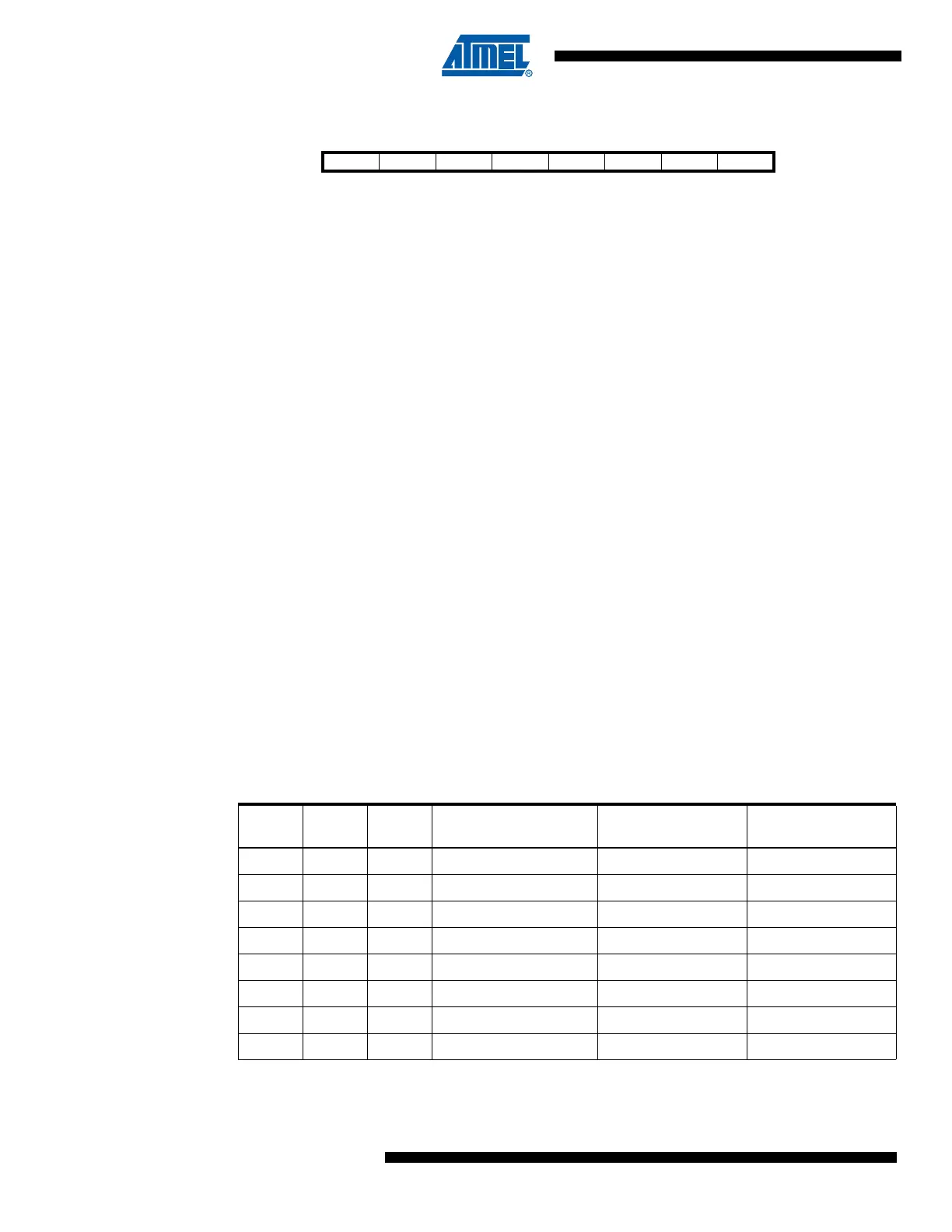
• Bits 2..0 – WDP2, WDP1, WDP0: Watchdog Timer Prescaler 2, 1, and 0
The WDP2, WDP1, and WDP0 bits determine the Watchdog Timer prescaling when the Watch-
dog Timer is enabled. The different prescaling values and their corresponding Timeout Periods
are shown in Table 7-6.
Bit 76543210
– – – WDCE WDE WDP2 WDP1 WDP0 WDTCR
Read/Write R R R R/W R/W R/W R/W R/W
Initial Value00000000
Table 7-6. Watchdog Timer Prescale Select
WDP2 WDP1 WDP0
Number of WDT
Oscillator Cycles
Typical Time-out at
V
CC
= 3.0V
Typical Time-out at
V
CC
= 5.0V
0 0 0 16K cycles 17.1 ms 16.3 ms
0 0 1 32K cycles 34.3 ms 32.5 ms
0 1 0 64K cycles 68.5 ms 65 ms
0 1 1 32/64K cycles 0.14 s 0.13 s
1 0 0 256K cycles 0.27 s 0.26 s
1 0 1 512K cycles 0.55 s 0.52 s
1 1 0 1,024K cycles 1.1 s 1.0 s
1 1 1 2,048K cycles 2.2 s 2.1 s
 Loading...


