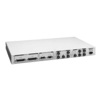
Specifications
DCX-127 Multifunction Module User’s Guide Page 31
PROGRAM CONTROL INPUT/OUTPUT
Input Configuration
8-bit parallel input. Input bits are software definable
to execute any valid keystroke sequence. An 8-byte
FIFO buffer allows asynchronous inputs.
Output Configuration
Pin 1
Delayed Gate. High-low transition occurs 50 ms to
12.75 s (in 50-ms steps) after sweep start.
Pin 2
Reset pulse, high during UTILITY RESTORE
command or following power cycling to the
DCX-127.
Pin 3 2 ms pulse when data is settled
Pin 4 2 ms pulse at end of settling delay
Pin 6 Sweep Gate, low during sweeps
Pin 7 A/B Gate; high when LVF is measuring channel A
Connectors 9-pin D-subminiature
DIGITAL INPUT/OUTPUT RELATED
Configuration
22-bit (21 bits data + sign) words, plus data
valid/new data strobes. 25-pin D-subminiature
connectors.
Maximum data rate
Approximately 8 msec/transfer, limited by computer
speed
AUXILIARY OUTPUT PORTS
Configuration
Three independent 8-bit parallel output ports. 9-pin
female D subminiature connectors