3.3 Loop topology (two-fibre loop)
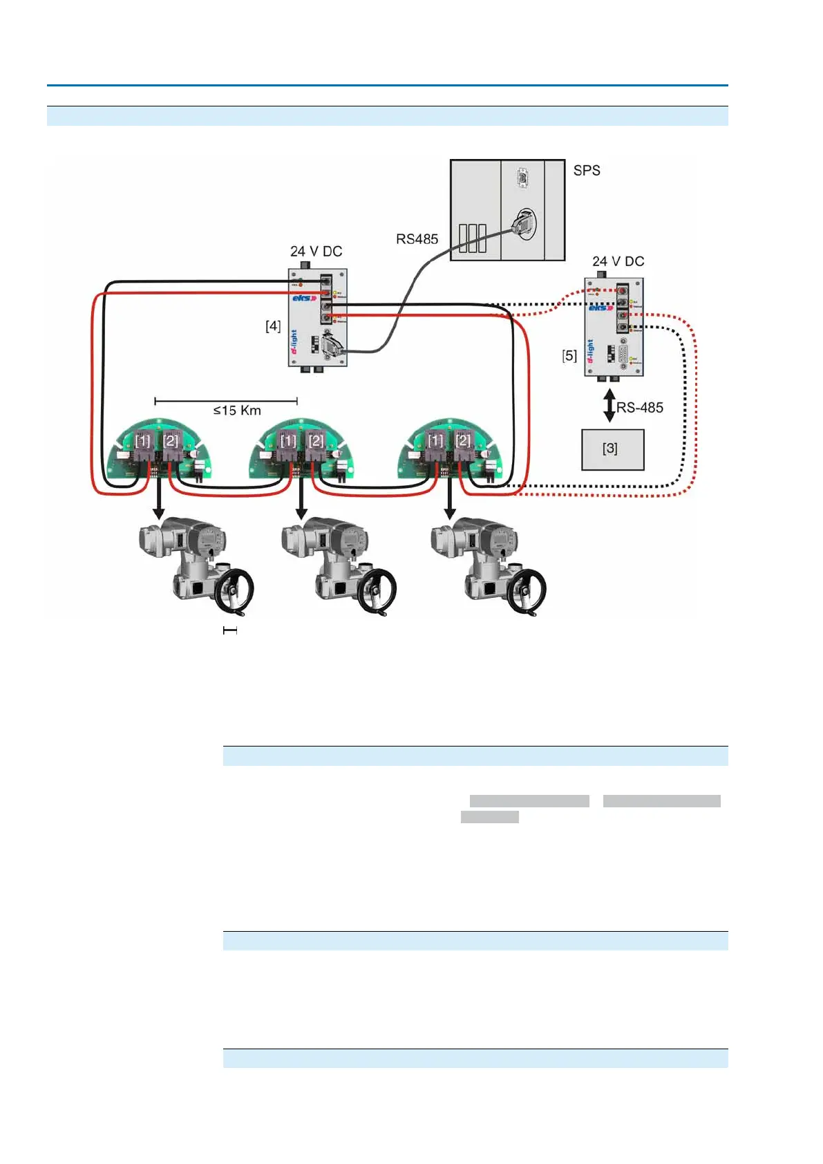
Figure 10: Structure for loop topology
Max. FO cable range in km (observe technical data!)
[1] Channel 1
[2] Channel 2
[3] Integration of any Profibus DP device (option)
[4] FO coupler at DCS (mandatory)
[5] FO coupler for any Profibus field device
Special features of loop topology
●
The interruption of an FO cable between two actuators is recognised by the
redundancy modules (via parameter FO cable monitoring = On (not final device)).
Both display and the bus indicate Wrn FOC.The network is then operated as
an optical line and all actuators remain available.
●
If one module fails (i.e. when the voltage supply is interrupted), only the actuator
connected to this module is disconnected from the loop, the remaining network
stays operative as a line. All other actuators remain available.
●
The actuators have a redundant FO cable connection with a standard Profibus
DP interface (not redundant).
Cable routing and PLC fault evaluation
●
To increase service safety, install cables for go-and-return in the loop on sepa-
rate lines.
●
To achieve complete monitoring of the redundant optical loop, all FO fault signals
(including the fault output of the FO coupler) at the master must be evaluated
by the PLC controls.
Setting response and slot time
The following settings should performed at the master:
10
Network topologies

 Loading...


