2.2 FO terminal compartment: open
The AUMA plug/socket connector (SDE bus) is equipped with a connection board
for connecting the fibre optic cables.When removing the cover [1], the connection
board is easily accessible.
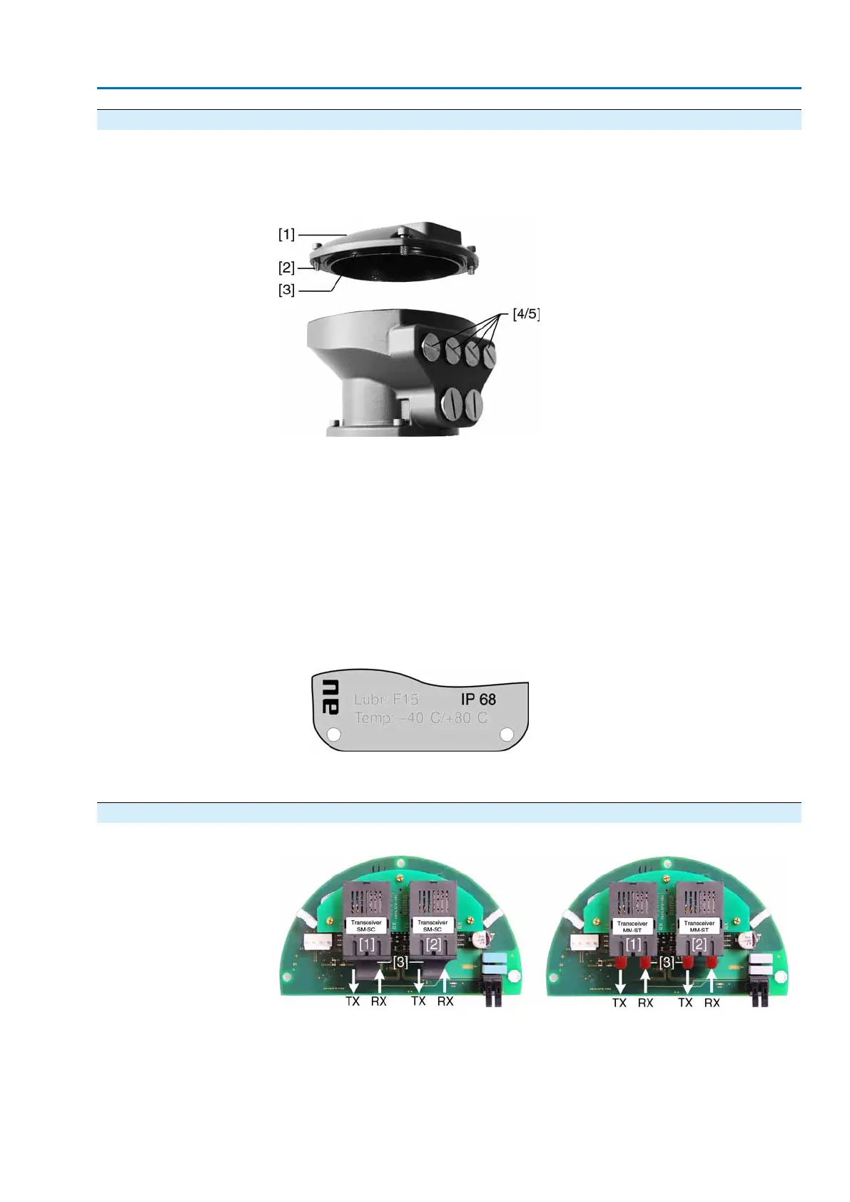
Figure 2: AUMA plug/socket connector SDE bus
[1] Cover (FO terminal compartment)
[2] Screws for cover
[3] O-ring
[4] Cable entries for fibre optic cables
[5] Blanking plugs
1. Loosen screws [2] and remove cover [1].
2. Insert cable glands suitable for FO cables.
➥
The enclosure protection IP… stated on the name plate is only ensured if suita-
ble cable glands are used.
➥
Example: Name plate for enclosure protection IP 68.
3. Seal unused cable entries [4] with suitable blanking plugs [5].
4. Insert the wires into the cable glands.
2.3 FO cables: connect
Figure 4: Connection board with connector types SC (left), ST (right)
[1] Channel 1
[2] Channel 2 (for loop or line topology)
[3] Protective cap/plug
TX Optical output
RX Optical input
5
FO connection

 Loading...


