2. FO connection
2.1 Basic information
Hazardous voltage!
Risk of electric shock. Failure to observe this warning can result in death or serious
injury.
→
The connection must be carried out exclusively by suitably qualified personnel.
→
Prior to opening: Disconnect both system and device from the mains.
→
Observe basic information contained in this chapter.
→
Observe safety instructions contained in the operation instructions pertaining
to the actuator.
Eye damage caused by open fibre optic cable ends!
→
NEVER look directly into open cable ends or FO cable connections.
Connection or receive problems when ignoring the installation instructions!
→
Only using FO cable connection (connector types) with the wiring techniques
indicated in these instructions.
→
Only mount connector types with locking mechanisms in the defined position.
→
Protect unused FO cable connections against contamination or dust with protec-
tive caps/plugs supplied by the factory.
→
Connect incoming FO cable with the optical receiver, the outgoing FO cable
with the optical sender. NOT vice versa!
→
Do NOT kink FO cables! Observe bending radius of cable manufacturer.
Cable and wire types
Table 1: Cables and wires according DIN VDE 0888 part 3:
Multi-mode 62.5 (50)/125 μm
Single-mode 9/125 μm
Fibre
62.5 (50)/125 μm glass fibre (multi-mode): 2,500 m
9/125 μm glass fibre (single-mode): 15 km
Range
Recommendation: < 2.0 dB/km (multi-mode) or < 0.4 dB/km
(single-mode)
Damping coefficient
Remove outer sheathing of FO cable at a length of approx. 42 cm to enable loop
wiring in the terminal compartment.
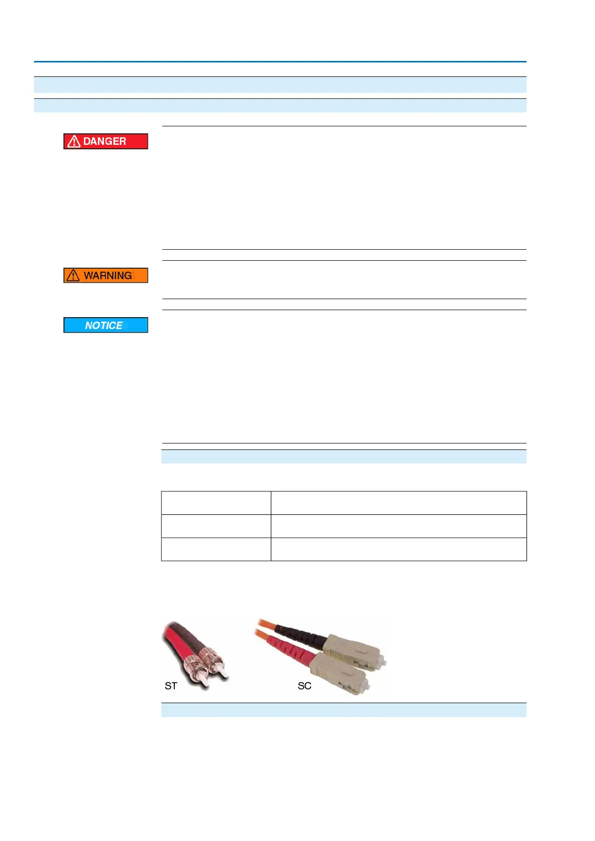
Figure 1: Plug types: ST or SC (depending on version)
Controls mounted to wall bracket
In the event of heavy vibration of the valve, we recommend mounting the actuator
controls separately from the actuator on a wall bracket. For information about the
wall bracket, refer to operation instructions for the actuator.
4
FO connection

 Loading...


