3. Network topologies
When connecting several terminal devices (actuators) in a network, the structure is
called network topology. AUMA offers 3 different network topologies.
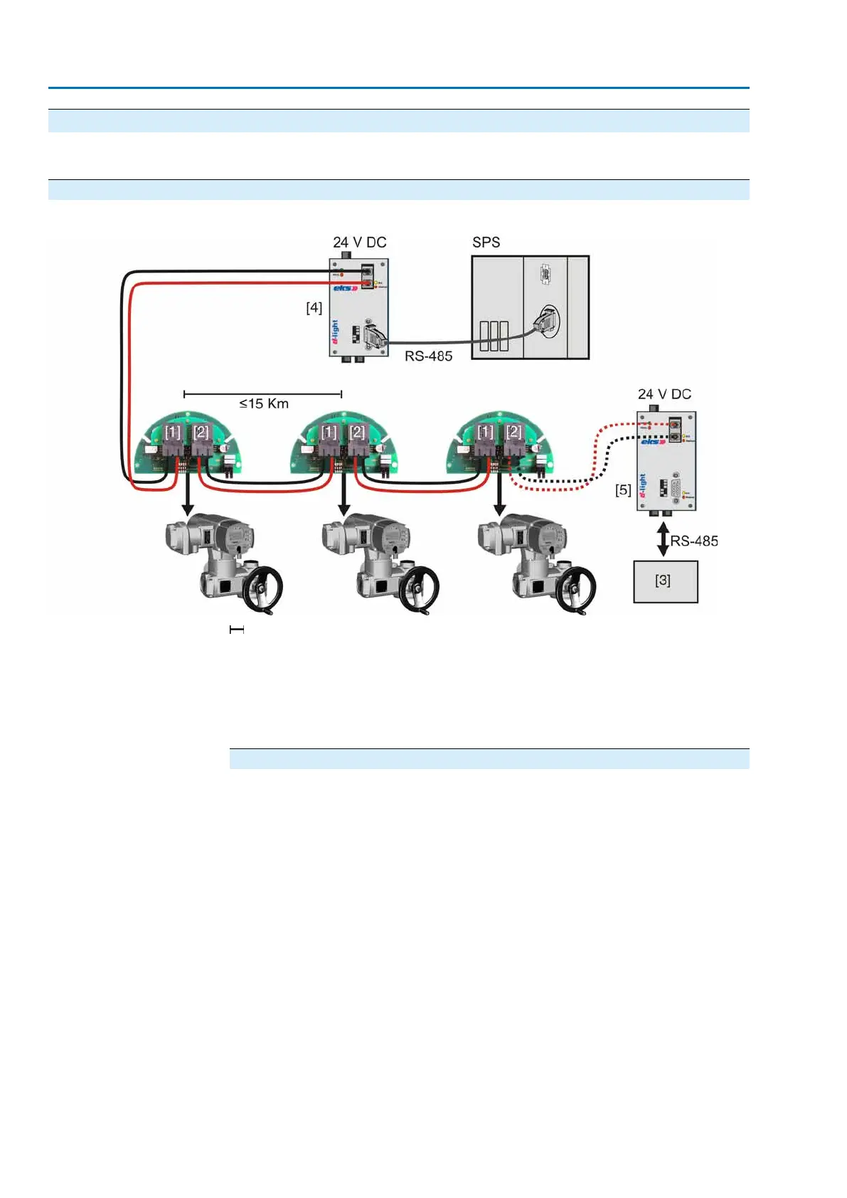
3.1 Line topology
Figure 8: Structure for line topology
Max. FO cable range in km (observe technical data!)
[1] Channel 1
[2] Channel 2
[3] Any Profibus DP device
[4] FO coupler at DCS (mandatory)
[5] FO coupler for any Profibus field device
Special features of line topology
The optical signal is converted into an electrical signal at each device. Prior to
transmission to the next device, the electrical signal is converted into an optical
signal.
Interruption of an FO cable (case A) or failure of an FO connection board (case B)
results in a loss of control for the subsequent actuators:
Case A
(standard)
As soon as the electrical connection is removed from the , the FO connection of this
actuator is no longer available. As a consequence, communication with the
subsequent actuators is lost.To prevent this, the FO connection used in the can also
be externally supplied with 24 V DC.
Case B
(option)
As soon as the actuator is switched off (motor voltage), the FO connection board of
this actuator is no longer available. As a consequence, communication with the
subsequent actuators is lost.To prevent this, the complete can be externally supplied
with 24 V DC.
8
Network topologies

 Loading...


