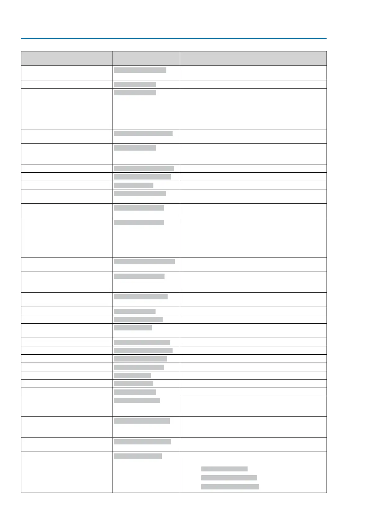
DescriptionDesignation
(process representation)
Prm-Text-Def GSD file
Received setpoint cannot be performed as the positioner is
not available.
Bit: Setpoint disabled
(55) = "Bit: Wrong command"
Motor protection tripped.
Bit: Thermal fault
(56) = "Bit: Thermal fault"
●
When connecting to a 3-ph AC system and with internal
24 V DC supply of the electronics: Phase 2 is missing.
●
When connecting to a 3-ph or 1-ph AC system and with
external 24 V DC supply of the electronics: One of the
phases L1, L2 or L3 is missing.
Bit: Phase failure
(57) = "Bit: Phase fault"
The phase conductors L1, L2 and L3 are connected in the
wrong sequence.
Bit: Incorrect phase seq
(58) = "Bit: Wrong phase sequence"
Due to insufficient mains quality, the controls cannot detect
the phase sequence (sequence of phase conductors L1, L2
and L3) within the pre-set time frame provided for monitoring.
Bit: Mains quality
(59) = "Bit: Mains quality"
Torque fault in direction CLOSE
Bit: Torque fault CLOSE
(60) = "Bit: Torque fault CLOSE"
Torque fault in direction OPEN
Bit: Torque fault OPEN
(61) = "Bit: Torque fault OPEN"
Torque fault in directions CLOSE or OPEN
Bit: Torque fault
(62) = "Bit: Torque fault"
Warning: Max. permissible operating time for an operation
(OPEN-CLOSE) exceeded
Bit: Op. time warning
(63) = "Bit: Operat. time warning"
Warning: Max. number of motor starts (starts) or max. run-
ning time/h exceeded
Bit: On time warning
(64) = "Bit: On time warning"
The internal 24 V AC voltage supply of the controls has ex-
ceeded the power supply limits.
The 24 V AC voltage supply is used to control the reversing
contactors, to assess the thermoswitches, to supply the in-
ternal actuator heater and, as an option, to generate the 115
V AC supply for the customer.
Bit: 24 V AC internal
(65) = "Bit: 24 V AC, internal"
The 24 V DC auxiliary voltage (e.g. for supply of the control
outputs) is outside the supply voltage limits.
Bit: 24 V DC control volt.
(66) = "Bit: 24 V DC control volt."
The internal 24 V DC supply voltage of the controls for
supply of the electronic components is outside the supply
voltage limits.
Bit: 24 V DC internal
(67) = "Bit: 24 V DC, internal"
The external 24 V DC voltage supply of the controls has
exceeded the power supply limits.
Bit: 24 V DC, external
(68) = "Bit: 24 V DC, external"
Collective signal 14: Internal error
Bit: Internal error
(69) = "Bit: Internal error"
Collective signal 15: Internal warning
Bit: Internal warning
(70) = "Bit: Internal warning"
No actuator reaction to operation commands within the set
reaction time.
Bit: No reaction
(71) = "Bit: No reaction"
Incorrect configuration, i.e. the current setting is invalid.
Bit: Configuration error
(72) = "Bit: Configuration error"
Parameter not available
Bit: Temp. fault controls
(73) = "Bit: Temp. fault controls"
Parameter not available
Bit: Temp. fault motor
(74) = "Bit: Temp. fault motor"
Parameter not available
Bit: Temp. fault gear
(75) = "Bit: Temp.fault gearbox"
Heater failure at actuator (control unit)
Bit: Wrn heater
(76) = "Bit: Wrn heater"
Real time clock has not yet been set.
Bit: RTC not set
(77) = "Bit: RTC not set"
Parameter not available
Bit: Wrn humidity
(78) = "Bit: Wrn humidity"
Warning:
Position feedback of actuator was not yet referenced for
limit end positions.
Bit: WrnRefActPos
(79) = "Bit: WrnRefActPos"
Warning:
Current position feedback signal range is outside the per-
missible range.
Bit: WrnSigRgeActPos
(80) = "Bit: WrnSigRgeActPos"
Warning:
A signal loss has occurred for actuator position feedback.
Bit: WrnSigLossActPos
(81) = "Bit: WrnSigLossActPos"
Warning: Actual position of actuator
Collective signal consisting of:
●
(79) Bit: WrnRefActPos
●
(80) Bit: WrnSigRgeActPos
●
(81) Bit: WrnSigLossActPos
Bit: WrnActPosition
(82) = "Bit: WrnActPosition"
14
Actuator controls
Commissioning AC 01.2/ACExC 01.2 Profibus DP
 Loading...


