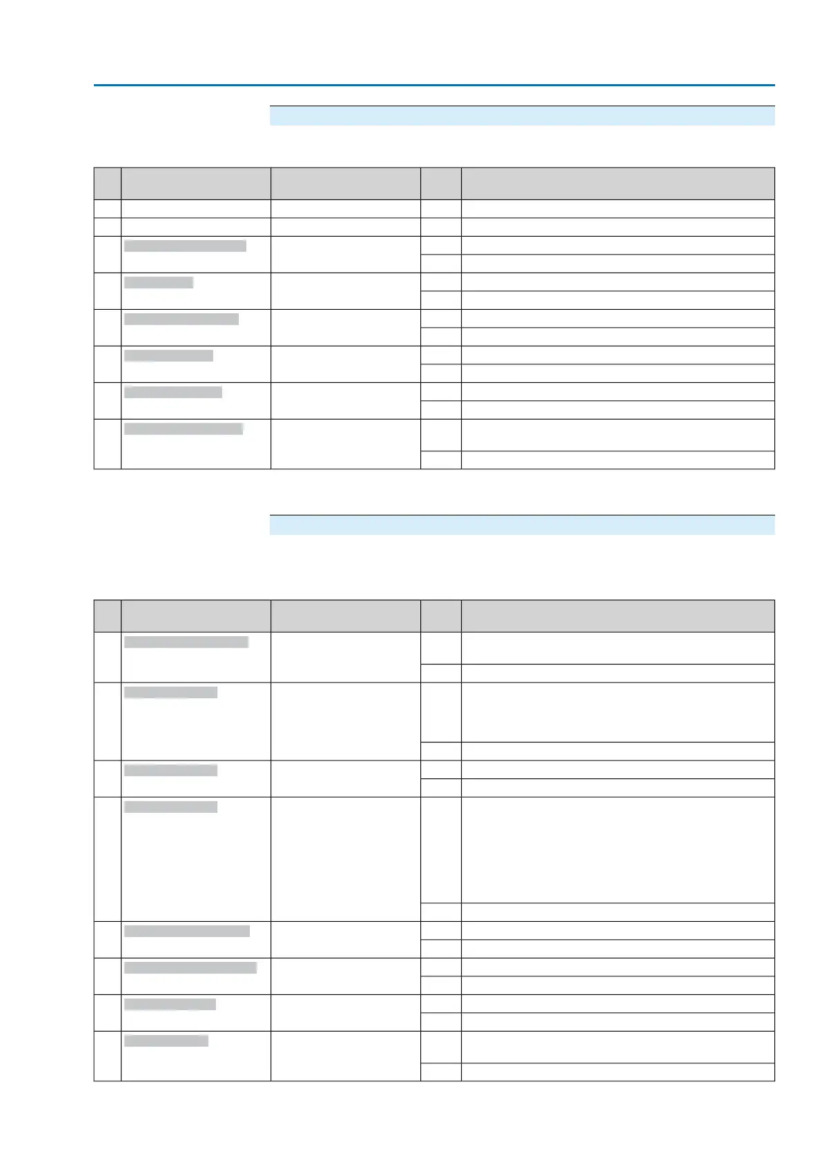
Byte 14: Not ready REMOTE 2
Table 11: Byte 14: Not ready REMOTE 2
DescriptionValuePrm-Text-Def GSD fileDesignation
(process representation)
Bit
No signal (reserved)——0
No signal (reserved)——1
The safety function of the SIL sub-assembly is active.1(207) = "SIL function act-
ive"
Bit: SIL function active
1)
2
No signal.0
Actuator is in operation mode Disabled.1(107) = "Bit: Disabled"
Bit: Disabled
3
No signal0
By-pass of interlock function is active.1(121) = "Bit: Bypass Inter-
lock"
Bit: Interlock by-pass
4
No signal0
Partial Valve Stroke Test (PVST) is active.1(116) = "Bit: PVST active"
Bit: PVST active
5
No signal0
Operation mode Service is active.1(51) = "Bit: Service active"
Bit: Service active
6
No signal0
Manual operation is active (handwheel is engaged); op-
tional signal
1(54) = "Bit: Handwheel
active"
Bit: Handwheel active
7
No signal0
The safety function indications via fieldbus are for information only and must not be used as part of a safety function.The I/O signals of
the SIL module must be used for this purpose.
1)
Byte 15: Fault 1
The fault signals contain the causes why the actuator cannot be operated.
Table 12: Byte 15: Fault 1
DescriptionValuePrm-Text-Def GSD fileDesignation
(process representation)
Bit
Incorrect configuration, i.e. the current setting of the actu-
ator controls is invalid.
1(72) = "Bit: Configuration
error"
Bit: Configuration error
0
Configuration is ok.0
Due to insufficient mains quality, the controls cannot de-
tect the phase sequence (sequence of phase conductors
L1, L2 and L3) within the pre-set time frame provided for
monitoring.
1(59) = "Bit: Mains quality"
Bit: Mains quality
1
No signal0
Motor protection tripped1(56) = "Bit: Thermal fault"
Bit: Thermal fault
2
No signal0
●
When connecting to a 3-ph AC system and with intern-
al 24 V DC supply of the electronics: Phase 2 is
missing.
●
When connecting to a 3-ph or 1-ph AC system and
with external 24 V DC supply of the electronics: One
of the phases L1, L2 or L3 is missing.
1(57) = "Bit: Phase fault"
Bit: Phase failure
3
No signal0
Torque fault in direction OPEN1(61) = "Bit: Torque fault
OPEN"
Bit: Torque fault OPEN
4
No signal0
Torque fault in direction CLOSE1(60) = "Bit: Torque fault
CLOSE"
Bit: Torque fault CLOSE
5
No signal0
Collective signal 14: Internal fault1(69) = "Bit: Internal fault"
Bit: Internal error
6
No internal fault0
No actuator reaction to operation commands within the
set reaction time.
1(71) = "Bit: No reaction"
Bit: No reaction
7
No signal0
27
Actuator controls
AC 01.2/ACExC 01.2 Profibus DP Description of the data interface