Byte 16: Fault 2
The fault signals contain the causes why the actuator cannot be operated.
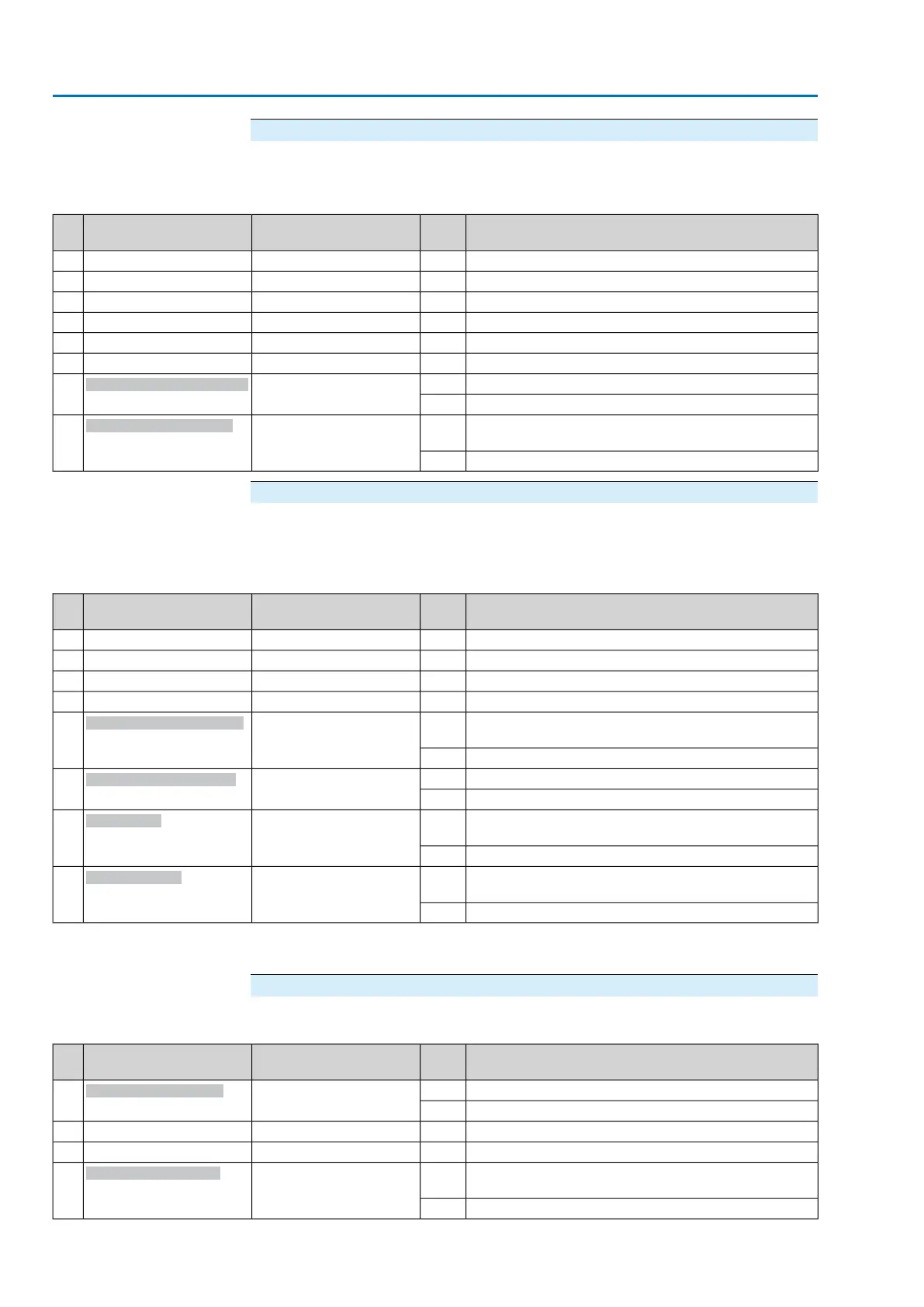
Table 13: Byte 16: Fault 2
DescriptionValuePrm-Text-Def GSD fileDesignation
(process representation)
Bit
No signal (reserved)——0
No signal (reserved)——1
No signal (reserved)——2
No signal (reserved)——3
No signal (reserved)——4
No signal (reserved)——5
Configuration error of REMOTE interface active.1(123) = "Bit: Config error
remote"
Bit: Config. error REMOTE
6
No signal.0
The phase conductors L1, L2 and L3 are connected in
the wrong sequence.
1(58) = "Bit: Wrong phase
sequence"
Bit: Incorrect phase seq
7
Phase sequence is ok.0
Byte 17:Warnings 1
The warning signals are for information only and do not interrupt or disable an
operation (as opposed to faults).
Table 14: Byte 17: Warnings 1
DescriptionValuePrm-Text-Def GSD fileDesignation
(process representation)
Bit
No signal (reserved)——0
No signal (reserved)——1
No signal (reserved)——2
No signal (reserved)——3
Warning: Limit value for Torque warning CLOSE ex-
ceeded
1(125) = "Bit: Torque wrn
CLOSE"
Bit: Torque warn. CLOSE
4
No signal0
Warning: Limit value for Torque warning OPEN exceeded1(124) = "Bit:Torque wrn
OPEN"
Bit: Torque warn. OPEN
5
No signal0
Warning: A SIL fault of the SIL sub-assembly has oc-
curred.
1(206) = "SIL fault"
Bit: SIL fault
1)
6
No signal0
Warning: No actuator reaction to operation commands
within the set reaction time.
1(71) = "Bit: No reaction"
Bit: No reaction
7
No signal0
The safety function indications via fieldbus are for information only and must not be used as part of a safety function.The I/O signals of
the SIL module must be used for this purpose.
1)
Byte 18:Warnings 2
Table 15: Byte 18: Warnings 2
DescriptionValuePrm-Text-Def GSD fileDesignation
(process representation)
Bit
Warning: Temperature within controls housing too high1(88) = "Bit: WrnControl-
sTemp"
Bit: Wrn controls temp
0
No signal0
No signal (reserved)——1
No signal (reserved)——2
The external 24 V DC voltage supply of the controls has
exceeded the power supply limits.
1(68) = "Bit: 24 V DC, extern-
al"
Bit: 24 V DC, external
3
No signal0
28
Actuator controls
Description of the data interface AC 01.2/ACExC 01.2 Profibus DP