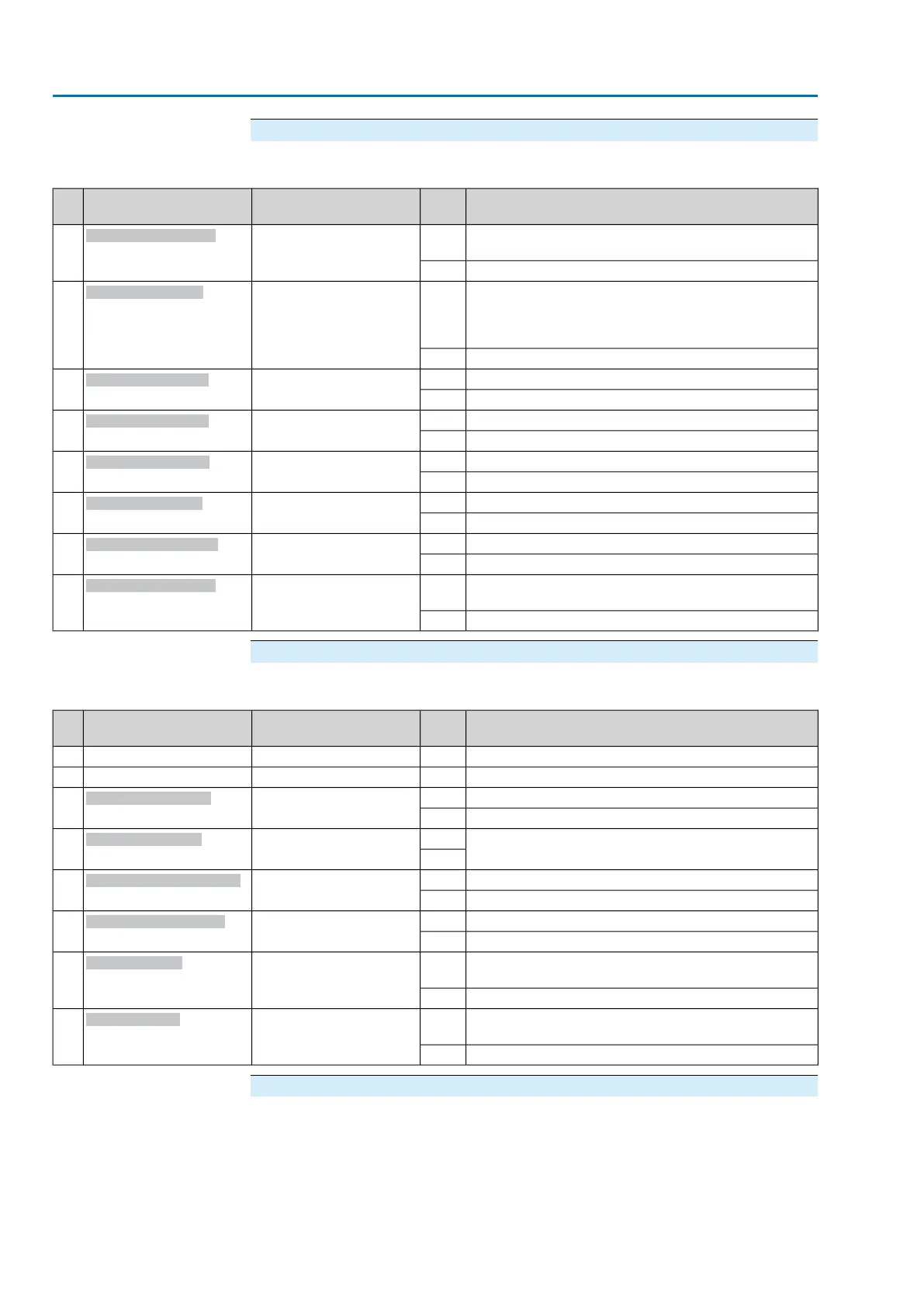
Byte 27: Out of specification 3
Table 22: Byte 27: Out of specification 3
DescriptionValuePrm-Text-Def GSD fileDesignation
(process representation)
Bit
Warning: FO cable system reserve reached (critical or
permissible Rx receive level)
1(111) = “Bit: Wrn FOC
budget”
Bit: Wrn FOC budget
0
No signal0
Warning:
Optical receiving signal (channel 1) incorrect (no or insuf-
ficient Rx receive level) or RS-485 format error (incorrect
bit(s))
1(83) = "Bit: Wrn FO loop"
Bit: Wrn FO cables
1
No signal0
Warning: Loss of signal analogue input 21(92) = "Bit: Wrn input AIN
2"
Bit: Wrn input AIN 2
2
No signal0
Warning: Loss of signal analogue input 11(91) = "Bit: Wrn input AIN
1"
Bit: Wrn input AIN 1
3
No signal0
Collective signal 15: Internal warning1(70) = "Bit: Internal warn-
ing"
Bit: Internal warning
4
No internal warning0
Warning: Max. number of motor starts (starts) exceeded1(85) = "Bit:WrnOnTiStarts"
Bit: WrnOnTiStarts
5
No signal0
Warning: Max. running time/h exceeded1(84) = "Bit: WrnOnTiRun-
ning"
Bit: WrnOnTiRunning
6
No signal0
Warning: Max. permissible operating time for an operation
(OPEN-CLOSE) exceeded
1(63) = "Bit: Operat. time
warning"
Bit: Op. time warning
7
No signal0
Byte 28: Out of specification 4
Table 23: Byte 28: Out of specification 4
DescriptionValuePrm-Text-Def GSD fileDesignation
(process representation)
Bit
No signal (reserved)——0
No signal (reserved)——1
Warning: Loss of signal of actuator setpoint position1(95) = "Bit: WrnSetpoint-
Pos"
Bit: WrnSetpointPos
2
No signal0
Warning: A Partial Valve Stroke Test (PVST) should be
performed.
1(208) = "PVST required"
Bit: PVST required
3
0
Warning: FO cable connection not available.1(127) = "Bit: Wrn FOC
connection"
Bit: Wrn FOC connection
4
No signal0
The failure behaviour is active.1(30) = "Bit: Failure behav.
active"
Bit: Failure behav. act.
5
No signal0
Partial Valve Stroke Test (PVST) was aborted or could
not be started. Remedy: Perform RESET or restart PVST.
1(118) = "Bit: PVST abort"
Bit: PVST abort
6
No signal0
Partial Valve Stroke Test (PVST) could not be successfully
completed.
1(117) = "Bit: PVST fault"
Bit: PVST error
7
No signal0
Byte 29: Function check 1
Causes of the Function check signal in accordance with NAMUR recommendation
NE 107.
32
Actuator controls
Description of the data interface AC 01.2/ACExC 01.2 Profibus DP