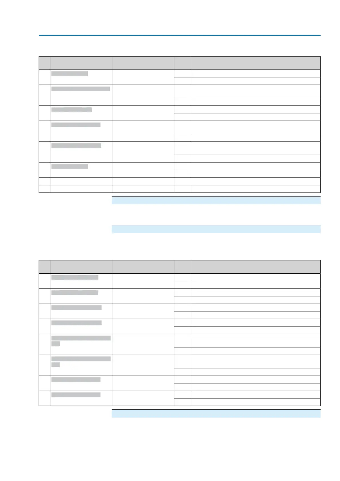
Table 24: Byte 29: Function check 1
DescriptionValuePrm-Text-Def GSD fileDesignation
(process representation)
Bit
Push button STOP of the local controls is operated.1(97) = "Bit: Local Stop"
Bit: Local STOP
0
No signal0
Selector switch is in position Local control (LOCAL) or
0 (OFF).
1(53) = "Bit: Sel. sw. not
REMOTE""
Bit: Sel. sw. not REMOTE
1
Selector switch is in position Remote control (REMOTE).0
Operation mode Service is active.1(51) = "Bit: Service active"
Bit: Service active
2
No signal0
Manual operation is active (handwheel is engaged); op-
tional signal
1(54) = "Bit: Handwheel
active"
Bit: Handwheel active
3
No signal0
Operation mode EMERGENCY stop is active (EMER-
GENCY stop button has been pressed).
1(50) = "Bit: EMCY stop
active"
Bit: EMCY stop active
4
EMERGENCY stop button not pressed (normal operation).0
Partial Valve Stroke Test (PVST) is active.1(116) = "Bit: PVST active"
Bit: PVST active
5
No signal0
No signal (reserved)——6
No signal (reserved)——7
Byte 30: Function check 2
The contents are reserved for further Function check signals in accordance with
NAMUR recommendation NE 107.
Byte 31: Status fieldbus
Information on the fieldbus status.
Table 25: Byte 31: Status fieldbus
DescriptionValuePrm-Text-Def GSD fileDesignation
(process representation)
Bit
Channel 1 is the active operation command channel.1(99) = "Fieldbus Channel
1 active"
Bit: Channel 1 active
0
No signal0
Channel 2 is the active operation command channel.1(100) = "Fieldbus Channel
2 active"
Bit: Channel 2 active
1
No signal0
Channel 1 is in the data exchange state.1(109) = “Bit: Pb DataEx
Ch1”
Bit: Channel 1 DataEx
2
No signal0
Channel 1 is in the data exchange state (DataEx).1(110) = “Bit: Pb DataEx
Ch2”
Bit: Channel 2 DataEx
3
No signal0
No valid fieldbus communication via channel 1 (application
does not communicate with the DCS).
1(112) = “Bit: Fieldbus-
FailsafeAct.1”
Bit: Chan 1 FailState field-
bus
4
No signal0
No valid fieldbus communication via channel 2 (application
does not communicate with the DCS).
1(113) = “Bit: Fieldbus-
FailsafeAct.2”
Bit: Chan 2 FailState field-
bus
5
No signal0
Fieldbus communication on channel 11(114) = “Bit: Chan1
BusComm”
Bit: Channel 1 activity
6
No signal0
Fieldbus communication on channel 21(115) = “Bit: Chan2
BusComm”
Bit: Channel 2 activity
7
No signal0
Byte 32: SIL indications
Causes of the Maintenance required signal in accordance with NAMUR
recommendation NE 107.
33
Actuator controls
AC 01.2/ACExC 01.2 Profibus DP Description of the data interface