4. Safety instrumented systems and safety functions
4.1. Safety instrumented system including an actuator
Typically, a safety instrumented system including an actuator is composed of the
components as shown in the figure.
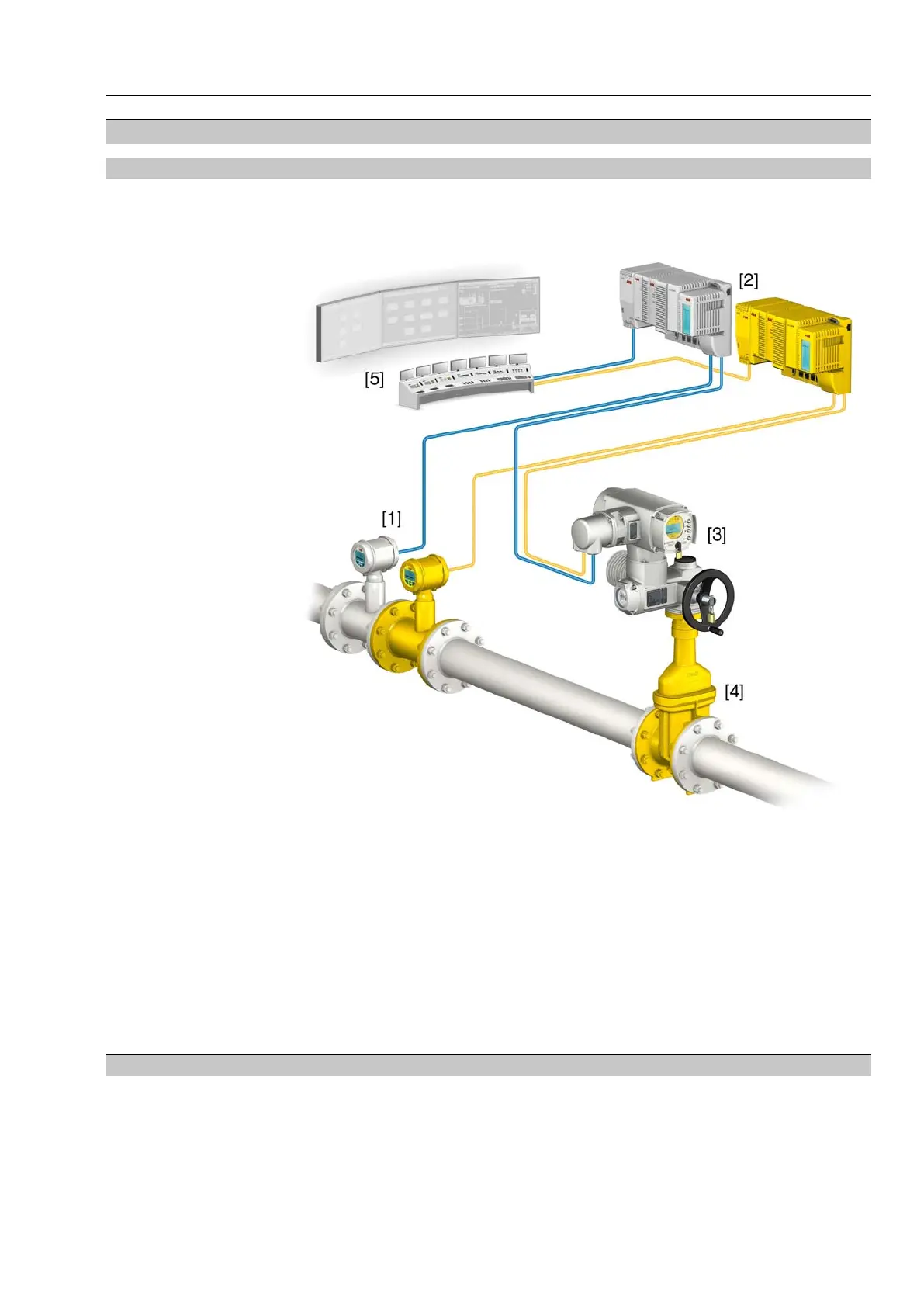
Figure 1: Typical safety instrumented system
[1] Sensor
[2] Controls (standard and safety PLC)
[3] Actuator with actuator controls
[4] Valve
[5] Process control system
The safety integrity level is always assigned to an overall safety instrumented system
and not to an individual component.
For an individual component (e.g. an actuator), safety instrumented figures are
determined.These figures are used to assign the devices to a potential safety integrity
level (SIL).The final classification of the safety instrumented system can only be
made after assessing and calculating all subsystems.
4.2. Safety functions
In calculating the safety actuator figures, the following safety functions are taken into
account:
●
Safe ESD function (Emergency Shut Down): Safe OPENING/CLOSING
- Redundant Safe ESDa and Safe ESDb signals (standard: low active) make
the actuator travel to the configured direction (OPEN/CLOSE).
11
Multi-turn actuators
SA 07.2 – SA 16.2/SAR 07.2 – SAR 16.2 Safety instrumented systems and safety functions

 Loading...


