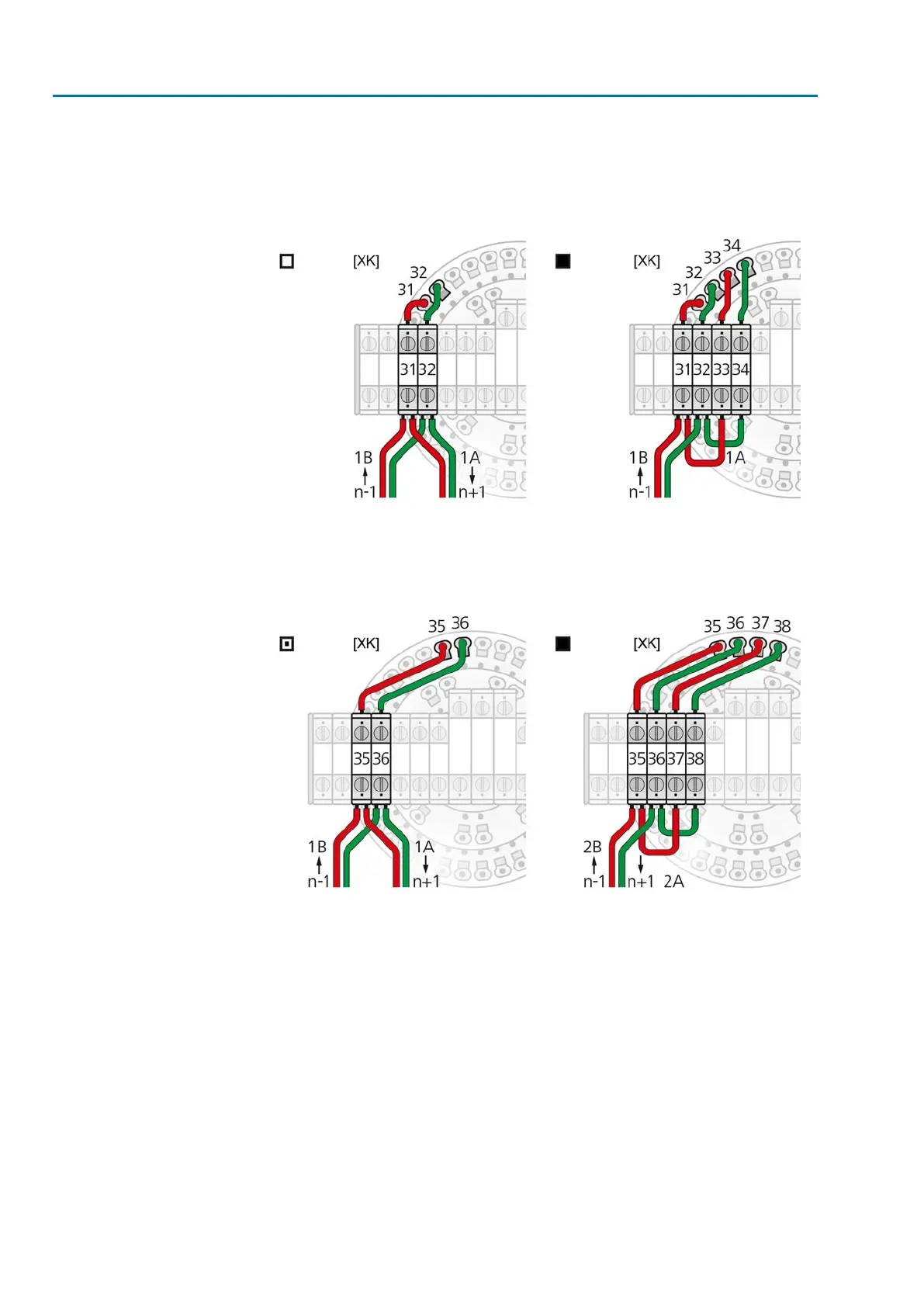
Connection with support terminals for line topology
When using solid cables (single or multiple strands), additional support terminals
must be used.The support terminals (terminal blocks) are mounted above the terminal
carrier.
Figure 31: Terminal assignment of support terminals: Channel 1 (1A/1B)
[XK] Terminal assignment according to wiring diagram (customer connection):
□
Terminals 31 and 32 if another fieldbus device follows
■
Terminals 31 – 34 if the actuator is the last fieldbus device
Figure 32: Terminal assignment of support terminals: Channel 2 (2A/2B)
[XK] Terminal assignment according to wiring diagram (customer connection):
▣
Terminals 35 and 36 if another fieldbus device follows
■
Terminals 35 – 38 if the actuator is the last fieldbus device
34
SAEx 07.2 – SAEx 16.2/SAREx 07.2 – SAREx 16.2 Control unit - electromechanical
Electrical connection ACExC 01.2 Intrusive Modbus RTU
 Loading...