For output drive type A (figure B), thread must match the thread of the valve
stem. If not ordered explicitly with thread, the stem nut is unbored or with
pilot bore when delivered. Finish machining of stem nut see below.
.
Check whether bore and keyway match the input shaft of valve/gearbox.
.
Thoroughly degrease mounting faces of multi-turn actuator and valve /
gearbox.
.
Apply a small quantity of grease to input shaft of valve / gearbox.
.
Place actuator on valve / gearbox and fasten with bolts (at least quality
8.8, refer to table 1) evenly crosswise.
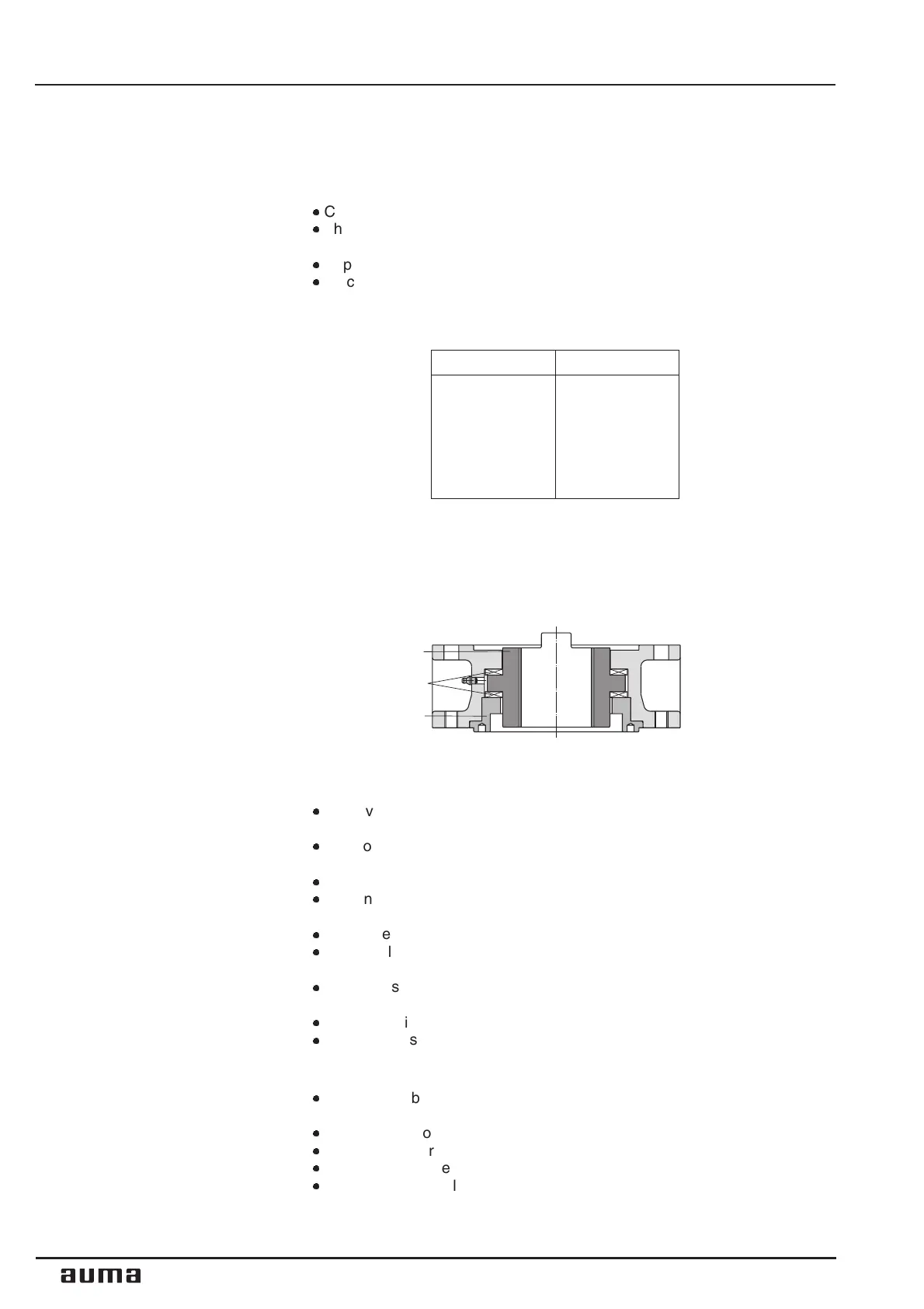
Finish machining of stem nut (output drive type A):
The output drive flange does not have to be removed from the actuator.
.
Remove spigot ring (80.2, figure B) with the help of a wrench or similar
tool from the mounting flange.
.
Take off stem nut (80.3) together with thrust bearing (80.01) and thrust
bearing races (80.02).
.
Remove thrust bearing and thrust bearing races from stem nut.
.
Drill and bore stem nut and cut thread
When fixing in the chuck, make sure stem nut runs true!
.
Clean the machined stem nut.
.
Apply ball bearing grease to thrust bearing and races, then place them on
stem nut.
.
Re-insert stem nut with thrust bearings into the mounting flange. Ensure
that dogs are placed correctly in the slots of the hollow shaft.
.
Screw in spigot ring until it is firm against the shoulder.
.
Press a few squirts of grease into the grease nipple with a grease gun.
Protection tube for rising valve stem
.
Protection tubes may be supplied loose. Wrap thread with hemp or Teflon
tape.
.
Screw protection tube into thread and tighten it firmly.
.
For corrosion protection KS/ KX, push down the seal to the housing.
.
Touch up possible defects in painting.
.
Check, wether sealing cap is available and without damage.
8
Multi-turn actuators SAM Ex 07.1 - SAM Ex 16.1 / SARM Ex 07.1 - SARM Ex 16.1
AUMA MATIC Ex Operation instructions
80.3
80.2
80.01/ 80.02
utput drive type A
stem nut
Figure B
8.8 T
A
(Nm)
M 6 10
M 8 25
M 10 50
M 12 87
M 16 220
Table 1
 Loading...


