9.3.1 Swing angle modification
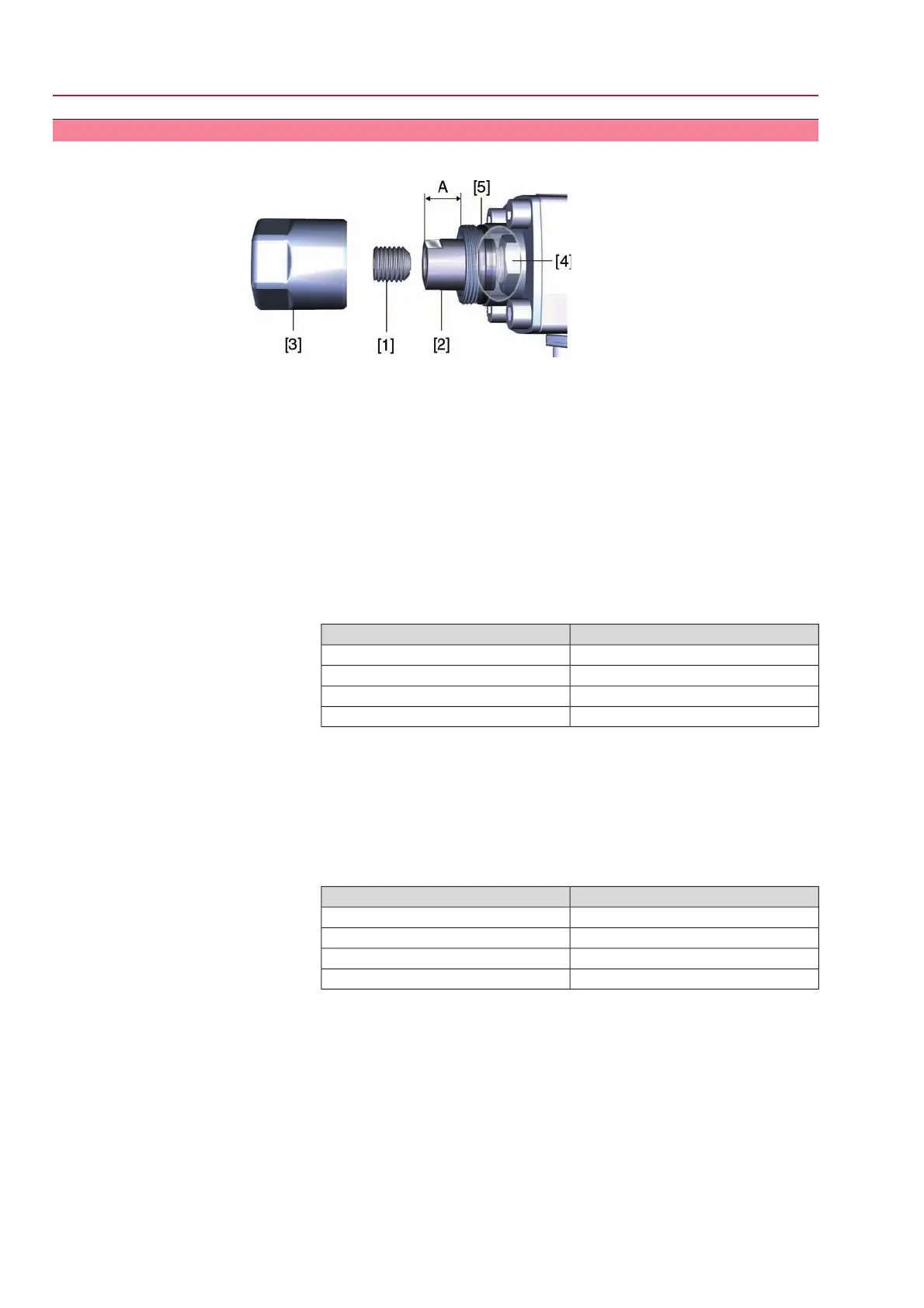
Figure 40: End stop
[1] Grub screw
[2] End stop nut
[3] Protective cap
[4] Travelling nut
[5] Sealing ring
1. Unfasten protective cap [3].
2. While holding end stop nut [2] in position with open end spanner, unfasten grub
screw [1].
3. Swing angle increase:
3.1 Turn end stop nut [2] counterclockwise. Do not exceed dimension A
max.
A max. [mm]Type
22SG 05.1/ SGR 05.1
22SG 07.1/ SGR 07.1
17SG 10.1/ SGR 10.1
23SG 12.1/ SGR 12.1
3.2 Move valve manually to the desired end position OPEN.
3.3 Turn end stop nut [2] clockwise until it is tight up to the travelling nut [4].
4. Swing angle reduction:
4.1 Move valve manually to the desired end position OPEN.
4.2 Turn end stop nut [2] clockwise until it is tight up to the travelling nut [4].
Do not fall below dimension A max.
A min. [mm]Type
10SG 05.1/ SGR 05.1
10SG 07.1/ SGR 07.1
08SG 10.1/ SGR 10.1
12SG 12.1/ SGR 12.1
5. Degrease mounting face of grub screw [1].
6. While holding end stop nut [2] in position with open end spanner fasten grub
screw [1] at 85 Nm.
7. Check O-ring [5] and replace if damaged.
8. Fasten protective cap [3].
40
SG 05.1 – SG 12.1/SGR 05.1 – SGR 12.1 Control unit: electromechanic
Commissioning (basic settings) AC 01.1 Intrusive Modbus RTU

 Loading...


