3. Turn potentiometer [1] slightly in opposite direction.
4. Perform fine-tuning of the zero point at external setting potentiometer (for remote
indication).
9.13 Electronic position transmitter RWG: set
— Option —
The electronic position transmitter RWG records the valve position. On the basis of
the actual position value measured by the potentiometer (travel sensor), it generates
a current signal between 0 – 20 mA or 4 – 20 mA.
Table 8: Technical data RWG 4020
3- or 4-wire systemWiring
TP_ _4/ _ _ _KMSTerminal plan
0 – 20 mA, 4 – 20 mAI
A
Output current
24 V DC, ±15 % smoothedU
V
Power supply
24 mA at 20 mA output currentIMax. current consump-
tion
600 ˖
R
B
Max. load
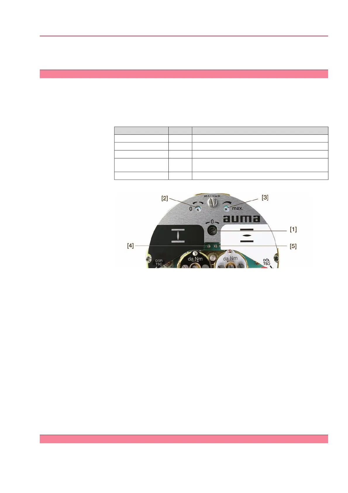
Figure 52: View of control unit
[1] Potentiometer (travel sensor)
[2] Potentiometer min. (0/4 mA)
[3] Potentiometer max. (20 mA)
[4] Measuring point (+) 0/4 – 20 mA
[5] Measuring point (–) 0/4 – 20 mA
1. Connect voltage to electronic position transmitter.
2. Move valve to end position CLOSED.
3. Connect ammeter for 0 – 20 mA to measuring points [4 and 5].
4. Turn potentiometer [1] counterclockwise to the stop.
5. Turn potentiometer [1] slightly in opposite direction.
6. Turn potentiometer [2] clockwise until output current starts to increase.
7. Turn potentiometer [2] in opposite direction until the following value is reached:
- for 0 – 20 mA approx. 0.1 mA
- for 4 – 20 mA approx. 4.1 mA
➥
This ensures that the signal remains above the dead and live zero point.
8. Move valve to end position OPEN.
9. Set potentiometer [3] to end value 20 mA.
10. Approach end position CLOSED again and check minimum value (0.1 mA or
4.1 mA). If necessary, correct the setting.
9.14 Mechanical position indicator: set
1. Place indicator disc on shaft.
53
SG 05.1 – SG 12.1/SGR 05.1 – SGR 12.1 Control unit: electromechanic
AC 01.1 Intrusive Modbus RTU Commissioning (basic settings)

 Loading...


