Table 16: Description of LEDs for I/O interface
DescriptionStatusLED
Module not poweredOffr
RESET mode
If LED e is simultaneously illumin-
ated in red: invalid firmware ver-
sion
single flash in green
PREOPERATIONAL modeBlinking in green
RUN modeIlluminated in green
●
Module not powered
●
If module is powered:
everything ok
Offe
●
Error
●
Status Reset
If LED r and simultaneously single
flash in green: invalid firmware
version
Illuminated in red
Initial state of corresponding digital
input
Illuminated in green1-6
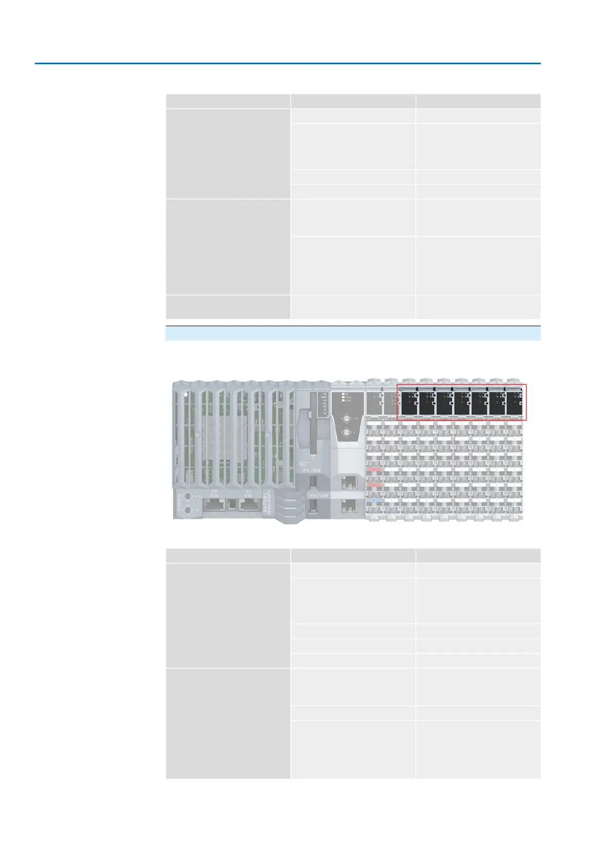
Communication interface
Figure 23: LEDs for communication interface
Table 17: Description of LEDs for communication interface
DescriptionStatusLED
Module not poweredOffr
RESET mode
If LED e is simultaneously illumin-
ated in red: invalid firmware ver-
sion
single flash in green
BOOT modeGreen double flash
PREOPERATIONAL modeBlinking in green
RUN modeIlluminated in green
●
Module not powered
●
If module is powered:
everything ok
Offe
I/O errorsingle flash in red
●
Error
●
Status Reset
If LED r and simultaneously single
flash in green: invalid firmware
version
Illuminated in red
24
SIMA² Master Station
Indications MODBUS RTU, MODBUS TCP/IP to DCS